 Indian Institute of Technology - Kharagpur
The electric circuit of the armature and the free body diagram of the rotor for the DC motor are shown in the following figure:
For this system, we have the following physical parameters:
• moment of inertia of the rotor (J)
• damping ratio of the mechanical system (b)
• electromotive force constant (
• armature resistance (R)
• armature inductance (L)
• input (V): source Voltage
• output (
Assumptions in Modelling a DC Motor:
• Demagnetizing effect of armature is neglected.
• Magnetic Circuit is assumed linear (no hysteresis and saturation). As a result all inductances (which came into play in dynamic analysis) are regarded as constant.
• The rotor and shaft is assumed to be rigid.
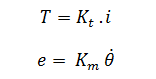
The motor torque, T, is related to the armature current, i, by a constant factor . The back emf, e, is related to the rotational velocity by the following equations:
In SI units,
From the figure above we can write the following equations based on Newton's law combined with Kirchhoff's law:
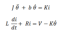
The time-domain model for dc motor is given below:

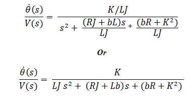
The transfer function of the dc motor system is given by:
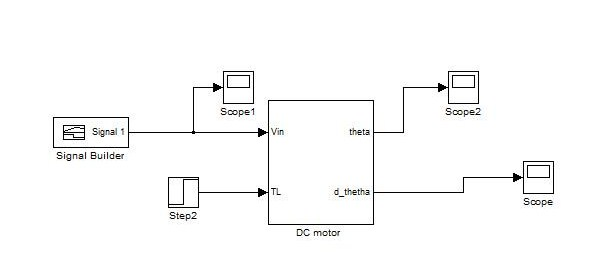
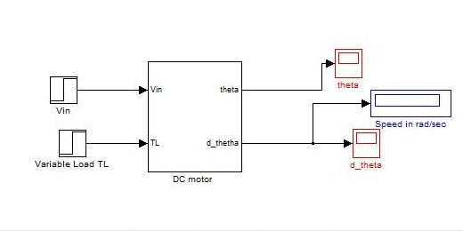
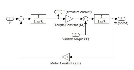
The block diagram of dc motor in s-domain is given below:
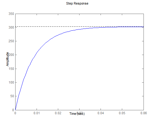
The impulse response and step response for an open loop dc motor system is given below. The dc motor is assumed to have the following parameters:
• moment of inertia of the rotor (J) =0.75e-07 Kg m2
• damping ratio of the mechanical system (b) = 1e-08 Nm/rad/s
• electromotive force constant (
• armature resistance (R)= 1.27 ohm
• armature inductance (L)= 0.000035 H

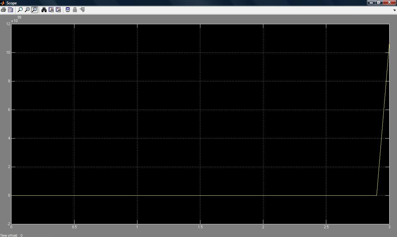
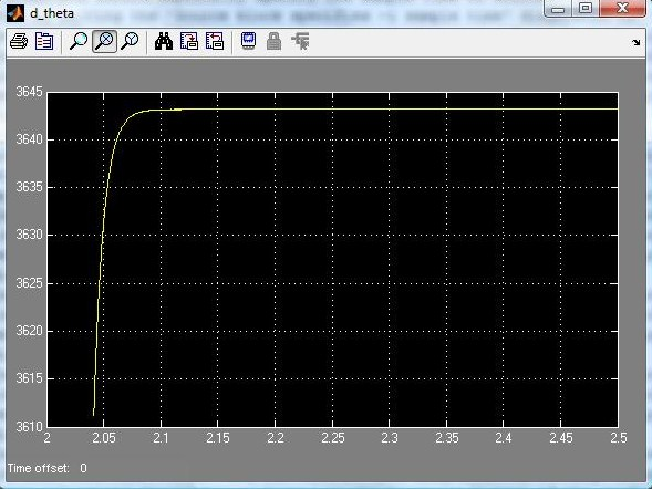
The step response for an open loop dc motor system is given below.
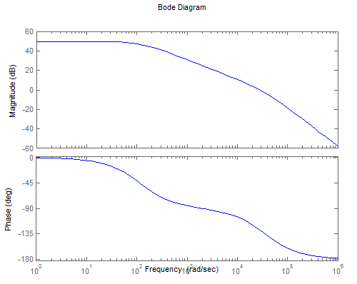
The Bode diagram of the system is shown in the figure below:
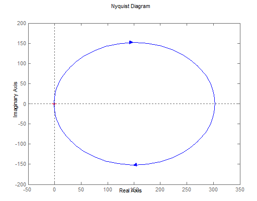
The Nyquist diagram of the system is shown in the figure below: