DC MOTOR
At the most basic level, electric motors exist to convert electrical energy into mechanical energy. This is done by way of two interacting magnetic fields -- one stationary, and another attached to a part that can move.
The basic principles of electromagnetic induction were discovered in the early 1800's by Oersted, Gauss, and Faraday. By 1820, Hans Christian Oersted and Andre Marie Ampere had discovered that an electric current produces a magnetic field.
In any electric motor, operation is based on simple electromagnetism. A current-carrying conductor generates a magnetic field; when this is then placed in an external magnetic field, it will experience a force proportional to the current in the conductor, and to the strength of the external magnetic field. As you are well aware of from playing with magnets as a kid, opposite (North and South) polarities attract, while like polarities (North and North, South and South) repel. The internal configuration of a DC motor is designed to harness the magnetic interaction between a current-carrying conductor and an external magnetic field to generate rotational motion.
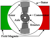
Every DC motor has six basic parts -- axle, rotor (i.e. armature), stator, commutator, field magnet(s), and brushes. The stator is the stationary part of the motor -- this includes the motor casing, as well as two or more permanent magnet pole pieces. The rotor (together with the axle and attached commutator) rotate with respect to the stator. The rotor consists of windings (generally on a core), the windings being electrically connected to the commutator. The above diagram shows a common motor layout -- with the rotor inside the stator (field) magnets. The geometry of the brushes, commutator contacts, and rotor windings are such that when power is applied, the polarities of the energized winding and the stator magnet(s) are misaligned, and the rotor will rotate until it is almost aligned with the stator's field magnets. As the rotor reaches alignment, the brushes move to the next commutator contacts, and energize the next winding.
There are two kinds of DC motors, stepper motors and servo motors
STEPPER MOTORS VS SERVO MOTORS
To justly compare
stepper vs servo motors ,assuming the following:
-The
motors are of equal rated power
-Both motors we are comparing are
of same quality
-Servo is equipped with an encoder
-Stepper is
not equipped with an encoder
-The driver is assumed to provide the
same features excluding feedback options
-The Servo motors are of
DC Brushed type
Cost: The cost for a servo motor and servo motor system is higher than that of a stepper motor system with equal power rating. This feature would have to go to stepper motors. Steppers are generally cheaper than servo motors that have the same power rating.
Versatility:
Servo motors are very versatile in their use for automation and CNC
applications. Stepper motors are also very versatile in their use for
automation and CNC applications. Because of their simplicity stepper
motors may be found on anything from printers to clocks.
Reliability: This is a toss up because it depends on the environment and how well the motor is protected.The stepper takes this category only because it does not require an encoder which may fail.
Frame Sizes: Servo motors are availible in a wide variety of frame sizes, from small to large motors capable of running huge machines. Many of the motors come in NEMA standard sized. Stepper motors do not have as many size selections as servo motors in the large sizes. However stepper motors may still be found in a variety of NEMA frame sizes
Setup Complexity: Servo motors require tuning of the (PID) closed loop variable circuit to obtain correct motor function. Stepper motors are almost plug-and-play. They require only the motor wires to be wired to the stepper motor driver.
Motor Life: The brushes on servo motors must be replaced every 2000 hours of operation. Also encoders may need replacing. The bearing on stepper motors are the only wearing parts. That gives stepper motors a slight edge on life.
Low Speed High Torque: Servo motors will do fine with low speed applications given low friction and the correct gear ratio. Stepper motors provide most torque at low speed (RPM).
High speed High Torque: Servo motors maintain their rated torque to about 90% of their no load RPM. Stepper motors lose up to 80% of their maximum torque at 90% of their maximum RPM.
Repeatability Servo motors can have very good repeatability if setup correctly. The encoder quality can also play into repeatability. Because of the way stepper motors are constructed and operate they have very good repeatability with little or no tuning required.
Overload Safety: Servo motors may malfunction if overloaded mechanically. Stepper motors are unlikely to be damages by mechanical overload.
Power to Weight/Size ratio: Servo motors have an excellent power to weight ratio given their efficiency. Stepper motors are less efficient than servo motors which usually means a smaller power to weight/size ratio.
Efficiency: Servo motors are very efficient. Yielding 80-90% efficiency given light loads. Stepper motors consume a lot of power given their output, much of which is converted to heat. Stepper motors are usually about 70% efficient but this has some to do with the stepper driver.
Flexibility in motor resolution Since the encoder on a servo motor determines the motor resolution servos have a wide range of resolutions available. Stepper motors usually have 1.8 or 0.9 degree resolution. However thanks to micro-stepping steppers can obtain higher resolutions. This is up to the driver and not the motor.
Torque to Inertia Ratio Servo motors are very capable of accelerating loads. Stepper motors are also capable of accelerating loads but not as well as servo motors. Stepper motors may stall and skip steps if the motor is not powerful enough.
Least Heat production: Since the current draw of a servo motor is proportional to the load applied, heat production is very low. Stepper motors draw excess current regardless of load. The excess power is dissipated as heat.
Reserve Power and Torque A servo motor can supply about 200% of the continuous power for short periods. Stepper motors do not have reserve power. However stepper motors can brake very well.
Noise Servo motors produce very little noise. Stepper motors produce a slight hum due to the control process. However a high quality driver will decrease the noise level.
Resonance and Vibration Servo motors do not vibrate or have resonance issues. Stepper motors vibrate slightly and have some resonance issues because of how the stepper motor operates.
Availability: Servo motors are not as readily available to the masses as are stepper motors. Stepper motors are far easier to find than quality servo motors.
Motor Simplicity: Servo motors are more mechanically complex due to their internal parts and the external encoders. Stepper motors are very simple in design with no designed consumable parts.
Direct Drive Capability: Servo motors usually require more gearing ratios due to their high RPM. It is very rare to see a direct drive servo motor setup. Stepper motors will work fine in direct drive mode. Many people simple use a motor couple and attach the motor shaft directly to the leadscrew or ballscrew.
Power Range: Because servo motors are available in DC and AC servo motors have a very wide power availability range. The power availability range for stepper motors is not that of servo motors.
http://www.youtube.com/watch?v=oCDQslDd74s&feature=related SERVO MOTOR
http://www.youtube.com/watch?v=JcfUoUdpeoA STEPPER MOTOR
Electric motors are used to “actuate” something in your robot: its wheels, legs, tracks, arms, fingers, sensor turrets, or weapon systems. There are literally dozens of types of electric motors (and many more if you count gasoline and other fueled engines), but for amateur robotics, the choice comes down to these three:
In a continuous DC motor, application of power causes the shaft to rotate continually. The shaft stops only when the power is removed, of if the motor is stalled because it can no longer drive the load attached to it.
In a stepping motor, applying power causes the shaft to rotate a few degrees, then stop. Continuous rotation of the shaft requires that the power be pulsed to the motor. As with continuous DC motors, there are sub-types of stepping motors. Permanent magnet steppers are the ones you’ll likely encounter, and they are also the easiest to use.
A special “subset” of continuous motors is the servo motor, which in typical cases combines a continuous DC motor with a “feedback loop” to ensure accurate positioning. There are many, many types of servo motors; a common form is the kind used in model and hobby radio-controlled cars and planes.
With three common motor types for amateur robots to pick from — DC, stepper, and servo — it can be hard to know which one is best. The answer is not simple, because each motor type has its own pros and cons.
Bear in mind that all motors are available in different sizes.
Small motors are engineered for applications where compactness is valued over torque. While there are small high-torque motors, these tend to be expensive because they use rare earth magnets, high efficiency bearings, and other features that add to their cost.
Large motors may produce more torque, but also require higher currents. High current motors require larger capacity batteries, and bigger control circuits that won’t overheat and burn out under the load. Therefore, match the size of the motor with the rest of the robot. Don’t overload a small robot with a large motor when big size isn’t important.
When decided on the size of the motor, compare available torque after any gear reduction. Gear reduction always increases torque. The increase in torque is proportional to the amount of gear reduction: if the reduction is 3:1, the torque is increased by about three times (but not quite, because of frictional losses).
|
Motor Type |
Pros |
Cons |
|
Continuous DC |
|
|
|
Stepper |
|
|
|
R/C servo* |
|
|
JOINT SPACE CONTROL
http://www.youtube.com/watch?v=_WFzP7_EbdE
Joint Space Control includes: PD Control, Control Partitioning, Motion Control, Disturbance Rejection, Steady-State Error, PID Control, and Effective Inertia.
. Traditional Controllers
PID(Proportional-Integral-Derivative) type control
It is well known that the traditional PID type controller with fixed gains cannot meet the requirements of underwater vehicle control. However, Jalving used a simple PD controller for AUV steering Yaw control. Chellabi proposed a PD combined with an optimal error correcting term. In this controller, the AUV dynamics is linearized and decoupled into 6 siso second-order subsystems, and a linear PD controller combined with an optimal controller using LQR technique is used in controlling each subsystem.
Sliding mode control (SMC)
SMC technique is a nonlinear feedback control scheme. It requires a raw estimation of the system parameter and an estimation of the system uncertainty for the switching surface design and variable structure control law design. However, since the AUV system is inherently time-variant and nonlinear, SMC shows great potential in achieving stability and performance against parametric uncertainty and external disturbance. This makes SMC related controllers one of the most commonly used control scheme in underwater vehicles. The main endeavor of using this method is to reduce chattering. Yoerge], Doughert] and Rodrigues introduced the basic methodology of using mode control for AUV application. Healey used sliding mode control in speed control, steering control and diving control separately. In this scheme the sliding surfaceis designed by pole placement or by considering an LQR optimal control solution to ensure global asymptotic convergence.
Robust/optimal control
Based on optimal control theory, numerous robust control schemes have been developed, such as Linear Quadratic Gaussian. Triantafyllou proposed a robust control scheme based on the Smith Control and the LQG methodology. Lacaze used Bang- Bang control for AUV control. Conte[9] proposed a robust controller based on lyapunov method considering the hydraulic disturbance and model uncertainties as bounded perturbation.
Adaptive control
There are parameter uncertainties and unknown disturbances in the underwater vehicle hydrodynamics. Many researchers resorted to adaptive control to estimate the system parameter and then construct controllers. Cristi proposed a model-based adaptive controller. Goheen proposed two adaptive controllers: one identifies a linear model of the open loop process, then design an LQG regulator based on the identified model.
Hybrid Controllers
In addition to those listed above, several hybrid controllers have been proposed for AUVs. They aim at solving their own disadvantages using some compensation means.
Adaptive sliding mode control
As stated earlier, an estimation of the uncertainty bound is necessary to apply sliding mode control. Fossen proposed an adaptive sliding mode controller that compensates for the uncertainty in the input matrix, which is generated by the time varying behavior of the control input due to the thruster hydrodynamics, by adding a discontinuous term(sliding mode term) to an existing adaptive controller.
OPEN LOOP VS CLOSED LOOP
Systems in which the output quantity has no effect upon the process input quantity are called open-loop control systems.
Systems in which the output has an effect upon the process input quantity in such a manner as to maintain the desired output value are called closed-loop control systems.
Closed-loop control
can counteract against disturbances (negative feedback);
can become unstable, i.e. the controlled variable does not fade away, but grows (theoretically) to an infinite value.
can only counteract against disturbances, for which it has been designed; other disturbances cannot be removed;
cannot become unstable - as long as the controlled object is stable