OVERVIEW
MECHANICAL
The body of the AUV is designed to implement a differential motion based control with two heave and two surge thrusters. The vehicle consists of a Main Hull, IMU enclosure and 4 Thrusters all mounted onto an Aluminium Frame. The Main Hull will have a diameter of 26 cm, and it will house the various electronic components and battery. The thrusters are placed so as to provide maximum control. All the thrusters have been accommodated as close as possible to the corresponding planes of center of gravity so as to minimize the unbalanced roll, pitch and yaw moments generated due to thrusters. The frame is made up of L cross section bars. The frame is implemented to provide rigidity and strength, and also to provide protection to the main hull in case the AUV collides with a wall in the arena. Enough clearance has been provided between the end cap and the sway thruster in order to accommodate water tight connectors to be attached to end cap.
AUV CAD Model
Exploded View
Torpedo and Dropper Design
The design of the torpedo is made such that the CG(center of gravity) and the CB(center of buoyancy) coincides latitudinally ,to achieve stable equilibrium. The fin area and its distance from the CG of the torpedo is chosen such that it has the maximum stabilizing effect. Moreover drag analysis of the designed torpedo has been done using ANSYS FLUENT to achieve a streamlined design.
Torpedo
Fluent Analysis
ELECTRICAL
Sensors
- Depth
- Paroscientific, Inc. Digiquartz® Pressure Instrumentation Series 8WD Intelligent Depth Sensor
- Velocity
- LinkQuest ‘s NavQuest 600 Micro DVL
- IMU
- Xsens Motion Technologies MT9-B Moisture sensor
Embedded Systems
- ATmega16, USB-ISS Multifunction USB Communications Module, ADAM 4024
Vision
- Forward
- Logitech HD C310 camera
- Bottom
- Microsoft LifeCam HD 3000
Power Distribution
- 4 X Lithium Ion (11.1, 3000mAh)
- 1 X Lithium Ion (24V, 9000mAh)
Propulsion
- 4 X Seabotix BTD 150
- 4 X Technadyne
Motherboard
- Intel D425K Mini ITX Mother Board
Inertial Measurement Unit: An IMU with 9 output data (3 axis gyroscopic value, 3 Axis accelerometer,
and 3 Axis magnetometer data) will be used to get feedback in the form of Heading, Acceleration and
Euler angles.
Doppler Velocity Log(DVL): If required for better accuracy and performance Kraken will be using DVL. DVL
uses four Sonars to measure the velocity of AUV in water. By integrating the velocity information, DVL
will also give the XYZ co-ordinate information with respect to its initial Point. The DVL also gives
roll, pitch and yaw values.
Depth Sensor: Depth sensor is a piezoelectric pressure transducer which will provide depth data from
water surface.
Camera: Our AUV is equipped with two cameras, one forward facing and a second one facing down. They
provide us with 8-bit color image.
The embedded system is used mostly for sensing and actuating the mechanisms. ATmega16 is used to
interface a current sensor. The status of moisture sensor is also monitored via it. It also connects
to a LCD screen which displays the current value and the status of moisture sensor.
To communicate with the outside word such as to communication with mechanisms LED-LDR circuit is
used. One more ATmega16 monitors the LDR and on receiving the specified code actuated the desired
mechanisms.
Kraken is powered with two cameras. Front vision is acquired via Logitech HD C310 camera and Bottom vision is captured via Microsoft LifeCam HD 3000. Currently the front and bottom camera is mounted inside the main hull but soon we are going to mount the cameras outside the hull. We also will be shifting to stereo camera for the front vision so as we can get an estimate of an object from the vehicle.
Kraken is powered by 4 Lithium ion battery (11.1V, 3000mAh) and 1 Lithium Ion Battery
(24V, 9000mAh). 4 Lithium Ion battery powers the thrusters. This path is completely
independent of sensors to reduce any unwanted noise.
The other battery is connects to the power converters which powers the motherboard. This
battery also powers sensors after passing through a DC-DC converter.
Both of the batteries have monitoring system which does coulomb counting and makes the
system to shut down when it runs low.
SOFTWARE
We have followed the modular approach in making our software which helps us in tuning and testing the capabilities and tasks separately. ROS (Robot operating system) have been adopted for software development and synchronization ROS works on publisher subscriber based architecture by mean of message passing. Different packages have been built on ROS Stack. ROS helped us to develop modular software with different tasks kept at different ROS nodes. All the nodes have categorized in 4 different type of nodes.
- Control and Movement
- Image Processing
- Task Planner
- Sensor Data Acquisition
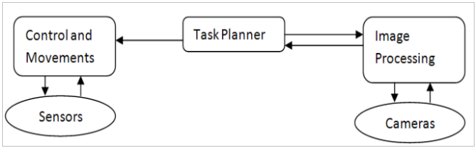
Control and Movement
In this first module basic maneuvering functions are written for forward, turn and heave. The Forward
function has code for heading control for which it interacts with the sensors interfacing module. We have
implemented a PID controller to achieve proper forward motion. It accepts positive value for forward motion
and nega value for reverse motion. The Turn function implements a self-designed control strategy to get
accurate turns. Here theta value is obtained from magnetic heading value from the IMU. This function
accepts positive value for Counter Clockwise turn and negative for Clockwise turn. For control, the
software uses simple and effective heuristic algorithms on top of classic Proportional Integral Derivative
(PID) controller.
For navigation system is dependent on AHRS implementation. In this application, the IMU is used only to
measure vehicle attitude (roll, pitch, and possibly heading). Sensors like a pendulum pot measure roll and
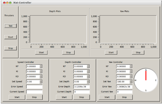
pitch, but have a relatively narrow response. User friendly graphical interface has been created for debugging
and visualization purpose
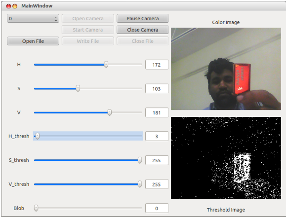
The images are acquired from the cameras using the camera interfacing nodes. These images are then thresholded
using their HSV (Hue Saturation Value) values. HSV values for objects and markers are pre-calibrated and
using the thresholding the similar color objects are isolated and filtered by shape and size constraints.
GUI has been developed to pre-calibrate the thresholding values and check the output of the applied
filters and various constraints. Once, a suitable fit is obtained, parameters like centroid and
orientation are sent back to Task Planner module to generate the appropriate control commands.
Underwater Images suffer from Non Uniform Lighting, Low Contrast and Diminished Colors Image enhancement
techniques were used to overcome degraded image.
This module knows about the different tasks to be performed in the full mission and the sequence of the occurrence This module calls the appropriate image processing function to isolate either a buoy, marker, L shaped obstacle, etc as per the task to be done. After getting the values of centroid and orientation, control commands are generated and control module executes the motion while getting feedback from the sensor module. An intelligent algorithm is required to perform each task task successful. A typical flow for path marker following is given in ().
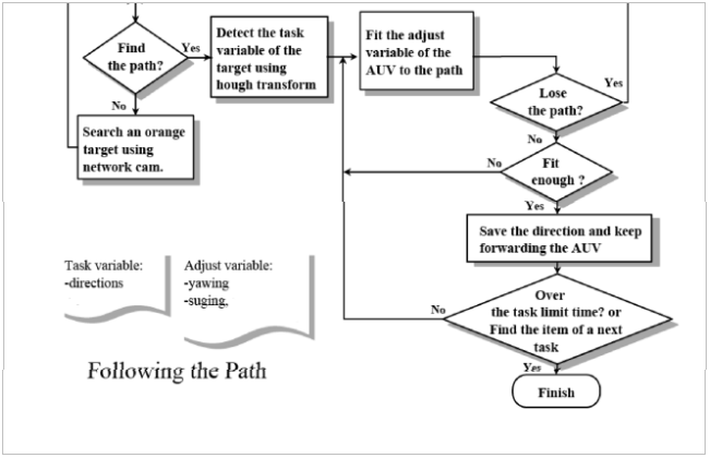
Task planner is also responsible for managing run time in most efficient way. A timeout is set for each task during a single mission run.
ABOUT US
The IIT Kharagpur Autonomous Underwater Vehicle Team (Team AUV) is a student group working in the field of autonomous underwater robotics. We design and build fully autonomous underwater robots for research and competitive purposes.