A slider crank
mechanism
converts——————
motion into
——————
motion.
Circular
into Linear.
What do you
understand by the term
path-length of the
slider ?
The
total distance covered
by the slider between
its two extreme
positions is called the
path length.
What is the
condition to rotate the
crank fully ?
L>
R+E where R is the
crank length,L is the
length of the link
connecting crank and
slider and E is the
offset of
slider.
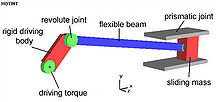
Name the type of
joints in the slider
crank mechanism.
Revolute
joint , prismatic
joint.