Objectives
• To demonstrate the operation of a CIM cell by providing remote access to a 3-D graphical animated simulation of the operations at different workstations
• To demonstrate the parts and production flow as well as interaction between the various components involved in the CIM cell
• To demonstrate the real time monitoring of production management functions in the CIM cell
What is Computer Integrated Manufacturing (CIM)?
Computer Integrated Manufacturing (CIM) is the technology for integration of all the operational and information processing functions in a manufacturing enterprise ranging from order receipt from customers to design, process planning, material requirement planning, manufacturing resources planning , purchasing, production planning and control, marketing and sales etc. The integration of the total manufacturing enterprise is accomplished through the use of computer and data communication technologies coupled with various managerial philosophies to improve the organizational and personal efficiencies.
What is CIM cell ?
CIM cell is an automated manufacturing system comprising of
a) one or more automated processing stations typically computer numerical control (CNC) machine tools,
b) one or more equipment for automated material handling and transport such as robots conveyors,
c) storage devices to store raw materials, work-in-progress and finished products that may include storage racks, and Automated Storage and Retrieval Systems (ASRS),
d) one or more quality control equipments such as machine vision system, Coordinate Measuring Machine(CMM), etc., and
e) a CIM software for overall integration, planning and control of the various operational and information processing function at individual stations of the CIM cell.
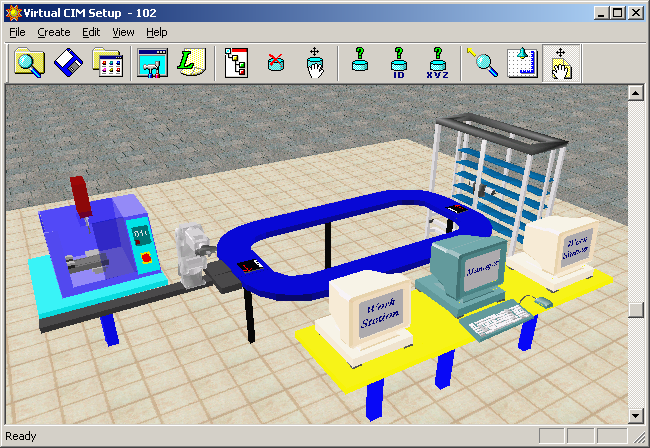
A Typical CIM cell
Fig shows the components of a typical CIM cell 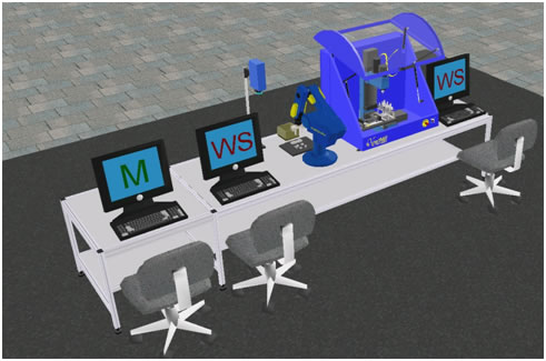
CNC MACHINE:
The machine shown in the cell is a vertical axis CNC milling machine that is equipped with an Automatic Tool Changer (ATC). It can be employed for two/three axes machining of plane and sculptured surfaces for various operations like milling, drilling and taping by using rotating tools. Loading and unloading of the parts at the CNC machine are carried out using robot.
ROBOT:
The robot shown in the cell consist of a five axes manipulator equipped with a gripper that is capable of automated material handling tasks such as packing and peaking of parts in/form machines, storage and retrieval of parts from storage devices, assembling of parts and handling of parts for quality control.
STORAGE STATION:
A storage station is used to retrieve raw materials prior to production, store work-in-process inventory, as well as finished products. The storage and retrieval at such stations are automated by robot manipulators.
QUALITY CONTROL STATION: The purpose of quality control station is to determine whether a product meets the quality control specifications as defined prior to the production process. The quality control station shown consists of a machine vision system equipped with a camera and image processing software. Handling of the parts at the quality control stations is carried out using robot.
CIM SOFTWARE: It provides a centralized control of on line production operations at each of the individual station devices of the CIM cell. It sends commands to station devices for starting and stopping the production and receives responses from the station devices which enable it to track the flow of parts during a CIM production cycle. It further maintains a database containing information on the physical and communication control configuration of the CIM cell, bill of materials used to produce each part, the order specifying the part to be produced, inventory of raw materials and parts, definition of machines in the CIM cell and manufacturing process that they can perform and the content of all the storage locations. It further provides a 3D animated graphical display of the CIM cell that can dynamically and accurately simulate the operations of all individual station devices in the CIM cell as well as provide status of the orders being processed, machine and storage device status, etc. in real time for online tracking of the CIM production cycle.
The CIM system consists of two cells.
Cell 1 is the storage, assembly and quality control station, which consists of the following equipments:
Cell 2 is a machining station, which consists of a CNC milling machine.
Figure below shows a 3D graphical view of the CIM cell.
For further details on the above equipments, please click here to visit the lab facilities page.
The Scorbot robot is used for CNC machine loading/unloading tasks, material handling for storage/retrieval of parts to/from storage as well as for presenting the part at the quality control station and for assembly.
The manufacturing operations that can be carried out in the CIM system are milling of plexiglass blocks, assembly operations, material handling between stations and the quality control of parts by machine vision.
The overall CIM system is run with a supervisory host control system consisting of two cell work station PC’s for the two cells and a host computer. The host computer allows management of CIM orders and operations via the CIM Manager – OpenCIM software system architecture. The OpenCIM offers various capabilities like CIM management, parts definition, order definition, machine definition, automatic CNC programs downloading for CNC machines, MRP package, 3D graphic animated simulation for on-line tracking of the whole system, reports generator for production reports, CIM scheduler module (GANNT chart).
The connections and the hierarchical relationships diagram of the CIM system is shown in figure below.
<insert figure as above>
The CIM Manager software via OpenCIM provides centralized control of on-line production activities. It sends commands to station devices and receives responses, which enable it to track the flow of parts during production
CIM CELL SETUP AND RUN SIMULATION (FROM SCRATCH)
Step to create cim cell set up
What is CIM cell ?
CIM cell is an automated manufacturing system comprising of
a)One or more automated processing stations typically computer numerical control (CNC) machine tools,
b)One or more equipment for automated material handling and transport such as robots conveyors,
c)Storage devices to store raw materials, work-in-progress and finished products that may include storage racks, and Automated Storage and Retrieval Systems (ASRS),
d)one or more quality control equipments such as machine vision system, Coordinate Measuring Machine(CMM), etc., and
e)A CIM software for overall integration, planning and control of the various operational and information processing function at individual stations of the CIM cell.
Step to create CIM CELL
1. Click new project. Define a project name.
2. Right click to select cim set up for create a cim cell.
3. Click view to select objects (table,robot,expwertmill,rack etc) for set up a cim cell
a. For robot first show envelope, connect all object to the robot in the robot workspace by selecting all objects.
b. For rack always select subtype (do not forget) Select utility programs
1. Select MRPcustomer order, select save button after entering customer description
2. Go to part definition, give supplied parts as cyl and pris(for cylindrical and prismatic parts respectively ) components, save supplied part
3. Go to products part, select new to give products part one by one by its subpart, process (GET, operation for purpose e.g. MILL, VIEWFLEX etc.) and parameters from where the parts being loaded and unloaded by the robot.
4. Save the product parts NB: for onfail process we have to define a parts in the phantom parts tab ,save all products part
5. Go to MRP->customer order, select parts name by drop down,enter required quantity, priority ,due date. save customer order
6. Go to manufacturing order, its already filled up as customer order. save manufacturing order by clicking MRP tab
Storage Manager :
1. Click to edit storage tab to give required quantity of rack for prismatic part and cylindrical parts .save the storage.
Click on default storage.
Click to save storage into the database.
Opencim Simulation program is now ready to run
To run a remote simulation experiment, perform the following steps:
Steps for downloading and installing Web Viewer client
1. First download and install the Web Viewer client by simply clicking here . Select run in order to run this program from its current location.
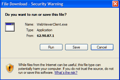
The Web Viewer Client Setup window will be displayed. When the installation is complete, click Finish
2.Select Save in order to save this program to a specified directory for future installations.
Steps of using Web Viewer for remotely viewing the grpahical simulation of the CIM cell
3.Open the Internet Explorer (version 6.0 and higher), and enter the following IP address in the address field: http://10.11.112.5/WebCimViewer/start.ASP
(Note: The Web Viewer application enables you to remotely access a specific CIM cell and track the production cycle from the various view tabs.) A webpage will be displayed as follows.
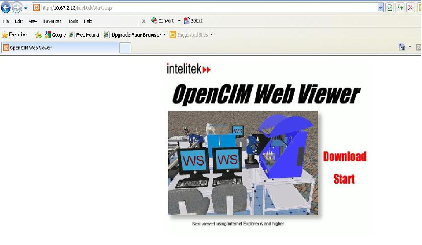
4. Click Start. The Open CIM Web Viewer appears displaying the Graphic Display Window as shown below with the following tabs to help in tracking the CIM production cycle.
• Graphic Display Tab to show a 3D display of the operations being performed in the CIM cell.
• View Scheduler Tab to display the scheduler information of the CIM cell.
• View Program Tab to display the A-Plan (meaning, the production work order) of the CIM cell.
• View Leaf Tab to display the production activities in the CIM cell.
• View Order Tab to display the current manufacturing order.
• View Storage Tab to display the current location of parts in the CIM cell.
• View Device Tab to display the actions performed by system devices.
• View Pallet Tab to display the pallets in the CIM cell and the current status of each pallet.
• Web Viewer Status Bar to display CIM cell information, such as current status, elapsed time, etc.
• View About Tab to display dialog with information about Web CIM Viewer software and CIM software of the Cell that is currently in view.
For details on how to use the above tabs for tracking the CIM production cycle, please refer to the video tutorials given in the User Guide page.