• To demonstrate inspection of parts by machine vision for quality control
• To demonstrate various steps of image processing
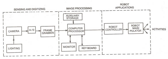
Machine Vision Machine vision may be defined as the process of extracting, characterizing and interpreting information from images of a three dimensional world.
Machine vision consists of three main functions:
Sensing and Digitizing: It is the process that yields a visual image of sufficient contrast that is typically digitized and stored in the computer memory.
Image processing and analysis: The digitized image is subjected to image processing and analysis for data reduction and interpretation of the image.
It may be further subdivided into:
Preprocessing – It deals with techniques like noise reduction and enhancement details Segmentation – It partitions an image into objects of interest.
Description – It computes various features like size, shape, etc. suitable for differentiating one object from another.
Recognition - It identifies the object by pattern matching.
Interpretation – It finally assigns a meaning to an ensemble of recognized objects in the scene Application: The current application of machine vision is inspection, part identification, location and orientation.
Performing Inspection by Pattern Matching
A pattern matching model or template of the object to be inspected is first created. This pattern will form the basis of performing inspection of the object. An image of the object is grabbed with a camera. In the next step, by using the image processing software, the pattern matching model created earlier is searched in the captured image for inspection of the object. The object is inspected for various aspects such as its position relative to the pattern matching model, the % score that reflects the correspondence between the image of the object and the pattern matching model, the dimensions of the object, perimeter of the object, surface area of the object and so on.
Sensing and Digitizing
Visual information is converted to electrical signals by visual sensors. When sampled spatially and quantized in amplitude, these signals yield a digital image.
Image sensing requires some type of imaging device (such as camera) and a digitizer which stores video frames in the computer memory.
Vision Cameras
:
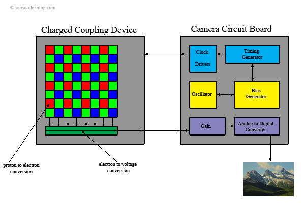
The principal imaging devices used for machine vision are television cameras, consisting of either a tube (vidicon camera) or the solid state camera (CCD, CID or silicon bipolar sensor cameras), and associated electronics.
Solid state imaging devices offer a number of advantages over tube cameras such as, lighter weight, smaller size, longer life and lower power consumption. However, the resolution of certain tubes is still beyond the capabilities of solid state cameras.
CCD Cameras :
A Charged Coupled Device (CCD) camera is shown in which an image is projected onto the CCD, which detects, stores and reads out the accumulated charge generated by the light pattern of the image. Light detection occurs through the absorption of light on a photoconductive substrate (e.g. silicon).
CCD devices can be subdivided into two categories: line scan sensors and area sensors.
Preprocessing :
Preprocessing deals with techniques like noise reduction and enhancement details. There are several approaches of preprocessing used in machine vision systems. The preprocessing approaches typical of the methods satisfying the requirements of computational speed and low implementation cost are discussed.
Noise reduction or smoothing :
Smoothing operations are used for reducing noise and other effects that are introduced in an image as a result of sampling, quantization, transmission or disturbances in the environment during image acquisition and digitizing. One straightforward technique for image smoothing is neighbourhood averaging in which a smoothed image is generated whose intensity at every point is obtained by averaging the intensity values of the pixels of the given image contained in a predefined neighbourhood of that point. One of the principal difficulties in this technique is that it blurs edges and sharp details. This blurring can be reduced by the use of so called median filters in which the intensity of each pixel is replaced by the median of the intensities in a predefined neighbourhood of that pixel, instead of by the average.
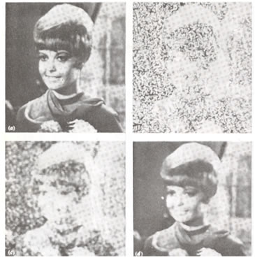
Noise reduction and smoothing operation(fig a)
Enhancement
:One of the principal difficulties in many low level vision tasks is to be able to automatically adapt to changes in illumination, which often plays a central role in determining the success of subsequent processing algorithms. Several enhancement techniques are available which address these and other similar problems. Enhancement is a major area of digital image processing and scene analysis.
Histogram equalization or histogram linearization technique is ideally suited for automatic enhancement and is based on a transformation function that is uniquely determined by the histogram of the input image. However, this method is not applicable when a priori information is available regarding a desired output histogram shape. Hence the concept is generalized by developing an approach known as histogram specification that is capable of generating an image with a specified intensity histogram.
Segmentation:Segmentation process subdivides a sensed image into constituent parts or objects. It is one of the most important elements of automated vision system, since it is at this stage of processing that objects are extracted from a scene for subsequent recognition and analysis.
Segmentation algorithms are generally based on one of the two basic principles: Similarity and Discontinuity.
The principal approaches in the first category are based on thresholding and region growing, and that in the second category are based on edge detection.
Thresholding :In its simplest form, thresholding is a binary conversion technique in which each pixel is converted into a binary value, either black or white. This is accomplished by using a frequency histogram of the image and establishing what intensity (gray level) is to be the border between black and white.
Region growing
:Once thresholding is established, the next step is to identify particular areas associated with objects within the image. Such regions usually possess uniform pixel properties computed over the area.
As the name implies, region growing is a procedure that group's pixels or sub regions into larger regions based on attribute similarities. The simplest approach is pixel aggregation, where one can start with a set of seed points and grow regions from these by appending to each seed those neighbouring pixels that have similar properties, e.g. intensity, texture or colour.
Edge detection :Edge detection considers the intensity change that occurs in the pixels at the boundary or edges of a part. Once a region of similar attributes has been found, the boundary can be determined by a simple edge following procedure. For a binary image, the procedure is to scan the image from the top left until a pixel within the region is encountered. For a pixel within the region, turn left and step; otherwise, turn right and step until the path has returned to the starting image, when the boundary is traversed. The contour – following procedure can extended to gray level images.
The set-up consists of the following:
• a USB colour camera mounted on a stand
For more details on the above please visit the Lab Facilities page by clicking Here
1. Place the part under the camera
2. Go to the start menu and run ViewFlex by selecting Programs->ViewFlex.The ViewFlex toolbar will be displayed as shown in figure. (insert snapshot of viewflex toolbar)
3. Click on the Image Processing Tools icon from ViewFlex toolbar to load Matrox Inspector 8.0.
4. Click on the camera icon to open the camera window. Click on Snapshot icon to grab(capture) the picture of the object and display it in a frame. The captured image will be put into the current frame of the image.
5. Click the ROI (Region of Interest) icon and outline the perimeter of the object.
6. Click on the Pattern Matching icon as shown in figure (insert screenshot of pattern matching dialog box) to display the Pattern Matching Model dialog box.
From the Dimension tab,you will see the object that was outlined using the ROI icon.
From the Search tab, click All.
From the Angle tab, check Enable search with rotate. Then enter 180 for Delta Negetive,and 180 for Delta Positive (this enables a full 360 degree search).
Click Search. This will bulid a Measurement Table containing all the positions of the object.
7. Save the Pattern Matching Model in the Pattern folder, located in the ViewFlex root folder. Ensure that the Pattern dialog box is selected when saving.
8. Open the result table and expand the pattern model in the folder tree. Check that the name you gave is listed in the tree.
9. Use this name when you find object.
10. Use step 4 to capture the image of the object. Click Search. This will bulid a Result Table containing all the positions of the object, Score(% matching with the template), and the Angle.
For remote experimentation, please book a slot in advance.
Click here to view the available slots.
Click here for live video streaming of the experiment