Objectives
•To demonstrate tool path planning for machining, generation of CNC part program containing G codes and M codes by manual part programming, and verification of the tool path by simulation.
• To demonstrate the machining operation on a 3 axis CNC Milling machine by downloading the Part program generated above to the CNC machine for execution
Computer Numerical Control (CNC) is a form of programmable automation, in which the mechanical actions of a machine tool are controlled by a program containing coded alphanumeric data the alphanumeric data represent the relative positions between the cutting tool and the workpart as well as other instructions needed to operate the machine.
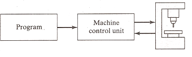
A CNC system consists of three basic components:
- the program of instructions or part program,
- the machine control unit (MCU), and
- the CNC machine tool
Process Planning
Process planning is an important manufacturing activity that interprets the part design specifications, then systematically determines the steps of manufacturing the part, according to the design specifications and within the limitations of the available manufacturing resources and their technological capabilities. The process planning in discrete parts manufacturing by machining may involve several or all of the following tasks:
Part program
The program of instructions, also called a part program, is the detailed step by step commands that direct the actions of the machine tool. The individual commands refer to positions of a cutting tool positions of a cutting tool relative to the worktable on which the workpart is fixtured. Additional instructions include spindle speed, feedrate, cutting tool selection, and other functions.The programmer prepares the NC code in low level machine language. The CNC code consists of blocks (also called lines), each of which contains an individual command for a movement or specific action. Each block is numbered. There are two major types of CNC codes in any program.
G codes and M codes
G-codes: They are preparatory functions, which involve actual tool moves (e.g. control of the machine tool). These include rapid moves, feed moves, dwells, roughing and profiling cycles
M-codes: They are miscellaneous functions, which include actions necessary for machining, but not those that are an actual tool movement movement (e.g. auxiliary functions). The include spindle on and off, program stops, and other similar related functions.
Machine Control Unit
The Machine Control Unit (MCU) consists of a microcomputer and related control hardware that stores the program of instructions and executes it by converting each command into mechanical actions of the machine tool. The related hardware of MCU includes components to interface with the machine tool and feedback control unit. The MCU also includes control system software, calculation algorithms, and translation software to convert the NC part program into a usable format for the MCU.
CNC Machine Tool
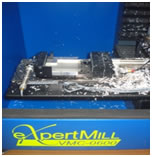
The third basic component of the CNC system is the machine tool. It performs the processing steps to transform the starting work material into a completed part. Its operation is directed by the MCU, which in turn is driven by instructions contained in the part program. It consists of worktable, spindle as well as the motors and control to drive them.
The figure above shows a three axis Vertical Machining Centre. It is the most common type of machining centre used and will be the type seen in this training program. It is called a Vertical Machining Centre because the orientation of the machine tool spindle is vertical. It is primarily employed for performing milling operation using rotating tools but it is often also capable of various other operations like drilling, boring, tapping. Plane and sculptured (3 –D) surfaces can be machined. The material to be machined is usually clamped to a table called the worktable. Special work holding devices like vises are sometimes also used to clamp the workpiece in place for machining. The figure below shows a dual axis pneumatic vise used to hold the workpiece.
The work table often is capable of moving in two perpendicular directions i.e. back and forth as well as at right angles, and the tool is capable of moving up and down relative the work table on the vertical machining centre as shown in the figure below. These three types of axis movements are enough to create many different types of workpieces. The size of the workpiece that the machining centre can handle is determined the range of movements of these three axes. In addition, the maximum power of the spindle motor and its maximum RPM determine the type of workpiece that the machine tool can handle.
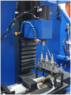
Many different types of tools are generally needed to create the various features of a workpiece. In a machining centre, these tools are commonly held in a tool storage device. The device which is used to automatically remove a tool from the spindle and load a new tool from the tool storage device is called an Automatic Tool Changer (ATC). Figure shows an ATC used on a Vertical Machining Centre.
Using the information contained in the part program, the CNC Machining Centre controls the various axis movements, starts and stops the spindle, sets the spindle speeds, sets the rate at which the tool feeds into the workpiece, and even changes the tools. All of the operations and functions of the machine tool are performed by motors. The motors are controlled by the Machine Control Unit as it runs the part program.
The set-up consists of the following
• 3-axis vertical CNC Milling machine,
with dual axis pneumatic vise for work holding,
and 4 station automatic tool changer (For details, visit the Lab Facilities page by clicking here)
• Software for simulation of tool path (For details, visit the Lab Facilities page by clicking here)
Preparation of a part program
Steps for System Startup
1. Turn on the power supply to the UPS of Workstation 1, UPS of the Robot Controller (N.B Power to the solenoid valves to the CNC is via this UPS) and power supply to the CNC controller.
2. Turn on the PC of WS1.
3. Turn on the CNC Controller.
4. Turn on the Remote Control Switch for the Compressor.
5. Open the valve of compressed air supply and make sure that the gauge pressure is 6 bar.
6. Make sure that the air dial indicator on the side of the CNC Mill is 6 bar.
7. Make sure that there are three tools in the Tool Changer and one tool inside the Spindle.
8. Make sure that there is no part in the vise.
9. Make sure that the vise is Open and has two Aluminium spacer and one plexiglass spacer.
10. Make sure that the CNC mill is clean.
11. Make sure that the Emergency Button on CNC Mill is not pressed.
12. Make sure that the spindle speed is CNC ON.
13. Log in to the Workstation 1.
14. Click on the CNCBase for Intelitek CNC icon.![]()
15. The CNC software will load.
Note: If you wish to run an existing program skip the following steps and proceed to step 22.
If you wish to write a new part program, proceed to the following steps.

Steps for preparation of a New Part Program
16.Select file>New
17.Write the Part program
A CNC part program is given below for machining the part shown in the figure.
N001 G90
N002 M6 T4
N003 G0 X0 Y0
N004 M3 S2000
N005 Z10
N006 X25 Y10
N007 Z2
N008 G1 Z-2 F100
N009 G2 Y40 R15 F200
N0010 Y10 R15
N0011 G1 Y20 F200
N0012 G2 Y30 R5 F200
N0013 Y20 R5
N0014 G1 Y10 F200
N0015 G1 Z-4 F100
N0016 G2 Y40 R15 F200
N0017 Y10 R15
N0018 G1 Y20 F200
N0019 G2 Y30 R5 F200
N0020 Y20 R5
N0021 G0 Z10
N0022 X0 Y0
N0023 M6 T1
N0024 M5
N0025 M30
Consider the block 'N001 G90', G 90 is the G-code for absolute programming.
Consider the block 'N002 M6 T4', M6 is the M-code for executing tool change. T4 specifies the tool to be used. Thus M6 T4 indicates to the MCU for changing the tool to tool number 4 which is in this case end milling cutter of diameter 10 mm.
Consider the next block 'N003 G0 X0 Y0' G0 is the Point-to-point (PTP) movement (rapid traverse) between previous point and end point defined in the current block. Thus G0 X0 Y0 indicates the command for moving the tool rapidly in PTP mode from the previous point (home position) to the end point (whose co-ordinates are X=0 and Y=0).
Consider the next block 'N004 M3 S2000'. M3 is the M-code for starting the spindle in clockwise direction. S2000 sets the spindle speed. Thus M3 S2000 indicates the command for starting spindle rotation at 2000 rpm.
Consider the next block 'N005 Z10'. It indicates the command for moving the tool rapidly in PTP mode from the previous point to the end point P0 whose co-ordinates are X=0, Y=0 and Z=10.
Consider the next block 'N006 X25 Y10'. It indicates the command for moving the tool rapidly in PTP mode from the previous point (whose co-ordinates are X=0, Y=0 and Z=10) to the end point (whose co-ordinates are X=25, Y=10 and Z=10).
Consider the next block 'N007 Z2'. It indicates the command for moving the tool rapidly from the previous point (whose coordinates are X=25, Y=10 and Z=10) to the end point (whose co-ordinates are X=25, Y=10 and Z=10).
Consider the next block 'N008 G1 Z-2 F100'. G1 is the G-code for linear interpolation movement. F100 is used to specify the feed rate. Thus G1 Z-2 F100 indicates the command for moving the tool in a straight line from the previous point (whose coordinates are X=25, Y=10 and Z=2) to the end point P1 (whose co-ordinates are X=25, Y=10 and Z=-2) at the designated feed rate of 100 mm/min.
Consider the next block 'N009 G2 Y40 R15 F200'. G2 is the G-code for circular interpolation, clockwise. R15 is used to specify the arc radius. Y40 is used to indicate co-ordinates of end point. F200 is used to specify the feed rate. Thus G2 Y40 R15 F200 indicates the command for moving the tool in a circular path having arc radius of 15 mm from the previous point P1 (whose co-ordinates are X=25, Y=10, Z=-2) to then end point P2 (whose co-ordinates are X=25, Y=40 and Z=-2) at the designated feed rate of 200 mm/min.

Consider the next block 'N0010 Y10 R15'. It indicates the command for moving the tool in a circular path having arc radius of 15 mm from the previous point P2 (whose co-ordinates are X=25, Y=40 and Z=-2) to the end point P1 (whose co-=ordinates are X=25, Y=10 and Z=-2).
Consider the next block 'N0011 G1 Y20 F200'. It indicates the command for the tool in a straight line from the previous point P1 (whose co-ordinates are X=25, Y=10, Z=-2) to the end point P3 (whose co-ordinates are X=25, Y=20 Z=-2) at designated feed rate of 200 mm/min.
Consider the next block 'N0012 G2 Y30 R5 F200'. It indicates the command for moving the tool in a circular path having arc radius of 5 mm from the previous point P3 (whose co ordinates are X=25, Y=20, Z=-2) to then end point P4 (whose co-ordinates are X=25, Y=30 and Z=-2) at the designated feed rate of 200 mm/min.
Consider the next block 'N0013 Y20 R5'. It indicates the command for moving the tool in a circular path having cutter radius of 5mm from the previous point P4 (whose co-ordinates are X=25, Y=30 and Z=-2) to the end point P3 (whose co-ordinates are X=25, Y=20 and Z=-2).
Consider the next block 'N0014 G1 Y10 F200'. It indicates the command for moving the tool in a straight line from previous point P3 (whose co-ordinates are X=25, Y=20, Z=-2) to the end point P5' (whose co-ordinates are X=25, Y=10 and Z=-2) at the designated feed rate of 200 mm/min.
Consider the next block 'N0015 G1 Z-4 F100'. It indicates the command for moving the tool in a straight line from previous point P5' (whose co-ordinates are X=25, Y=10 and Z=-2) to the end point P5 (whose co-ordinates are X=25, Y=10 and Z=-4) at the designated feed rate of 100 mm/min.
Consider the next block 'N0016 G2 Y40 R15 F200'. It indicates the command for moving the tool in a circular path of having arc radius 15 mm from the previous point P5 (whose co ordinates are X=25, Y=10 and Z=-4) to the end point P6 (whose co-ordinates are X=25, Y=40 and Z=-4) at the designated feed rate of 200 mm/min.
Consider the next block 'N0017-Y10 R15'. It indicates the command for moving the tool in a circular path of having cutter radius 15 mm from the previous point P6 (whose co-ordinates are X=25, Y=40 and Z=-4) to the end point P5 (whose co-ordinates are X=25, Y=10 and Z= 4).
Consider the next block 'N0018-G1 Y20 F200'. It indicates the command for moving the tool in a straight line from the previous point P5 (whose co-ordinates are X=25, Y=10 and Z=-4) to the end point P7 (whose co-ordinates are X=25, Y=20 and Z=-4) at the designated feed rate of 200 mm/min.
Consider the next block 'N0019-G2 Y30 R5 F200'. It indicates the command for moving the tool in a circular path of having arc radius 5 mm from the previous point P7 (whose co ordinates are X=25, Y=20 and Z=-4) to the end point P8 (whose co-ordinates are X=25, Y=30 and Z=-4) at the designated feed rate of 200 mm/min.
Consider the next block 'N0020-Y20 R5'. It indicates the command for moving the tool in a circular path of having arc radius 5 mm from the previous point P8 (whose co-ordinates are X=25, Y=30 and Z=-4) to the end point P7 (whose co-ordinates are X=25, Y=20 and Z=-4).
Consider the next block 'N0021-G0 Z10'. It indicates the command for moving the tool rapidly from the previous point (whose co-ordinates are X=25, Y=20 and Z=-4) to the end point (whose co-ordinates are X=25, Y=20 and Z=10).
Consider the next block 'N0022-X0 Y0'. It indicates the command for moving the tool rapidly from the previous point (whose co-ordinates are X=25, Y=20 and Z=10) to the end point P0 (whose co-ordinates are X=0, Y=0 and Z=10).
Consider the block 'N0023-M6 T1', M6 is the M-code for executing tool change. T1 specifies the tool to be used. Thus M6 T1 indicates to the MCU for changing the tool to tool number 1 which is in this case end milling cutter of diameter 3 mm.
Consider the block 'N0024-M5', M5 is the M-code for spindle stop.
Finally consider the block 'N0025-M30', M30 is the M-code for program stop.
18.To check for programming errors before running a part program select verify program.
19.Watch the Verify window for simulation of the tool path.
20.When the verification is completed, the normal program stop dialog box appears.
21.Select file> save as .nc file
Steps for running the CNC Part Program
22.Click on the Home icon![]()
23.Machine Home Window will load.

24.Click on the Home button
25.The machine will now home all three axes. Wait until the homing is completed.
26.Select file > open.
27.Navigate to the folder containing the File.
28.Select the file and click open.
29.Using tool path verification, you can check for programming errors before running a part program. Select Program > verify.
30.The verify program dialogue box appears.Check verify program then watch the verify window.
31.When the verification is completed, the normal program stop dialogue box appears. Click OK.
32.Before executing the program, make sure that all safety procedures have been taken.
33.Open the door of the CNC Milling Machine by clicking on the icon for Output 8 from the Outputs toolbar.
34.Open the jaws of the vise by clicking on the icon for Output 7 from the Outputs toolbar.
35.Load a raw stock into the vise manually.
36.Close the jaws of the vise by clicking on the icon for Output 7 from the Outputs toolbar.
37.Close the door of the CNC Milling Machine by clicking on the icon for Output 8 from the Outputs toolbar.
38.Select run/continue command from the program menu. The run program dialogue box appears.
39.Make sure that the Start Line box is set to line 1of the program.
40.Click the run settings buttons. The Run setting dialogue box appears.
41.Make desired changes in the Run setting dialog box, and select OK.
42.Check run button to begin run your program.![]() Run program menu is displayed as follows.
Run program menu is displayed as follows.

43.Please verify the ATC configuration message will be displayed.

44.Click on OK.
45.Configure ATC window will be displayed.

46.Look at the Mill and verify that the tool shown on the window is physically present in the spindle.
47.The program will run.
48.After the part machining is completed, wait until all operations have stopped.
Steps for System Shutdown
49.In CNCBase software, click on the red stop button and OK.
50.Click on the Home icon to home all the 3 axes of the machine and wait until homing is completed.
51.Open the door of the CNC Milling Machine by clicking on the icon for Output 8 from the Outputs toolbar.
52.Open the jaws of the vise by clicking on the icon for Output 7 from the Outputs toolbar.
53.Remove the machined part from the vise manually.
54.Close the door of the CNC Milling Machine by clicking on the icon for Output 8 from the Outputs toolbar.
55.Exit the CNCBase software do not save.
56.Shut down the PC.
57.Turn off the Mill controller.
58.Turn off the Workstation 1 UPS.
59.Turn off the Power supply to the Workstation.
60.Close the valve for compressed air supply.
61.Turn off the remote control switch for compressor.
62.Turn off the Mains Power Supply to the FMS Lab.
63.Downstairs, turn off the Mains power supply to the compressor.
For remote experimentation, please book a slot in advance.
Click here to view the available slots.
Click here for live video streaming of the experiment
Click here to launch CAPP software module