•To demonstrate robot trajectory planning and programming of a robot manipulator
• To demonstrate machine loading /unloading by using robot
Robot
An industrial robot is a reprogrammable, multifunctional manipulator designed to move material, parts, tools or other specialized devices through various programmed motions for the performance of a variety of tasks. It is reprogrammable in the sense that, when interfaced with a computer or a microprocessor, it can be edited to have a new program and information. It is multifunctional in the sense of its versatility i.e. it can perform various activities e.g. it can use an end effector to move materials and parts, it can actuate tools like painting gun for spray painting, welding gun for welding or assemble components of a part. The robot has a mechanical configuration called the manipulator arm with a gripper or end-effector at its free end to move from point to point or in a continuous path following some trajectory.
The components of a robot include:
- A base – fixed or mobile
- A manipulator arm with several degrees of freedom (DOF)
- An end-effector or gripper holding a part or a tool
- Drives or actuators causing the manipulator arm or end-effector to move in space
- Controller with hardware and software support for giving commands to the drives
- Sensors to feed back the information for subsequent actions of the arm or gripper as well as to interact with the environment in which the robot is working
- Interfaces connecting the robotic subsystems to the external equipment in the outside world
Robot Programming
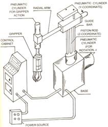
The robot manipulator can move its arm, wrist or gripper to the desired position describing a definite path.The figure below shows a Scorbot robot manipulator having five axes. Out of the five axes, the first three axes namely, wrist, shoulder and elbow constitute the body of the manipulator and are necessary to place the gripper of the robot at a definite location within the work envelope. The remaining two axes namely, the wrist pitch and the wrist rollare used to orient the gripper.
<insert video of robot joints moving>
The robot can be moved by using push buttons on a teach pendant box or automatically under some form of program control. Programming for generation of the path of a robot manipulator can be accomplished by various ways and this path is controlled by the robot controller by two methods:
- Point-to-point (PTP) control
- Continuous path (CP) control
Point-to-point (PTP) control
In the PTP programming method, the robot arm is taught to move from a point to another in its work envelope. Once the robot arm has been moved to a particular point by using the teach pendent, the locational point is recorded into the robot’s memory in the control by the programmer by pushing a ‘record’ button on the teach pendent. Next the robot arm is moved to a second point and this new point or position is recorded again by pushing the record button. This method is known as teaching. Thus, the point-to-point path generation in steps is done in the ‘teach’ mode. In ‘auto’ mode, all the points so recorded are played back and the robot arm starting from its first point moves through the programmed points till it reaches the end point. Figure below shows a PTP controlled path.
PTP control does not control the path taken by the robot to move from one point to the next. Control of the sequence of positions is adequate for certain applications like loading and unloading machines and spot welding.
In Continuous Path (CP) control, the path followed by the robot is controlled. In Continuous path motion, the discrete points programmed earlier may be traversed in a straight line or following a curve or an arc of a circle between the taught points as illustrated in Figure below. This is usually accomplished by making the robot move though a series of closely spaced points which describe the desired path. The individual points are defined by the controller rather than the programmer. When the program is on playback mode, the robot moves continuously through the points. Continuous path control is required for applications such as deburring, spray painting and arc welding.
Different robot programming languages are available for programming and control of the motions of robots.The robot programming language used for programming and control of the Scorbot robot that is used in this training program is Scorbase.
The set-up consists of the following
• 5-axis Robot manipulator with pneumatic gripper (For details, visit the Lab Facilities page by clicking here)
•Software for programming and control of robot (For details, visit the Lab Facilities page by clicking here)
•Software for simulation of robot
For more details on the above please visit the Lab Facilities page by clicking Here
Steps for System startup
1. Turn on the power supply to the UPS of work station 2 and robot controller.
2. Turn on the PC of workstation 2.
3. Turn on the robot controller.
4. Turn on the remote control switch for the compressor.
5. Open the valve of compressed air supply and make sure that the gauge pressure is 6 bar.
6. Make sure that the teach pendant is on the hanger and in auto mode & emergency button is not pressed.
7. Make sure that the emergency button of the robot is not pressed and red power LED is on.
8. Make sure that there is no part in robot gripper.
9. Make sure that the robot is in safe place to Home.
10. Log in to workstation 2.
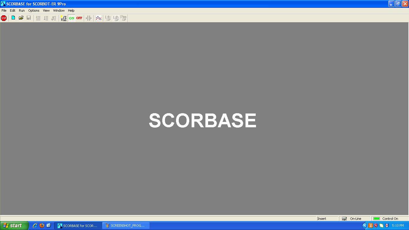
11. Click on the Scorbase standalone software icon. Scorbase software will load as shown below.
12. On the Scorbase software, click on the Home icon ![]() as shown below (If this icon is not active, click on the option & then on-line).
as shown below (If this icon is not active, click on the option & then on-line).
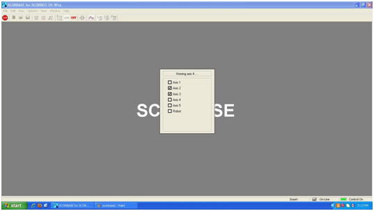
13. Homing menu will be displayed as shown below and robot will start its Homing procedure. Wait until all the boxes are ticked and robot has stopped Homing.
Steps for preparation of a new robot program
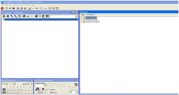
14. Go to file menu and select file > new project. The program window will be displayed on the left as shown in figure below.
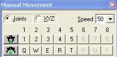
15. Next to set your program positions, go to the Manual movement dialog box menu as shown in the figure below. Move the robot to the desired position using this dialog box.
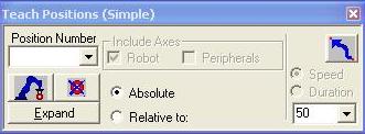
16. Go to Teach Position dialog box as shown in the figure below and type the position number in the position number field. Select absolute and click on record position to record the current robot position (in joint/xyz co-ordinate) to the position displayed in the position number field.
17. Repeat steps 15 and 16 to record all the desired position of the Robot trajectory.
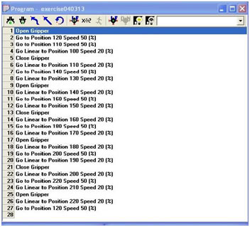
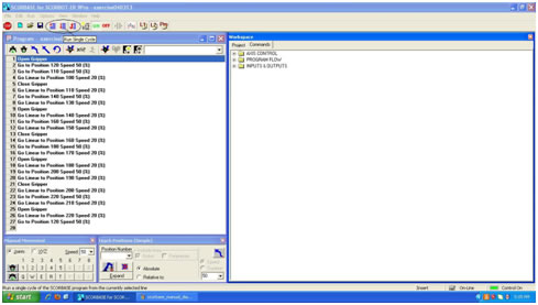
18. Go to the Program window as shown in figure below. The program window allows you to display and edit the programs that are there in the memory.
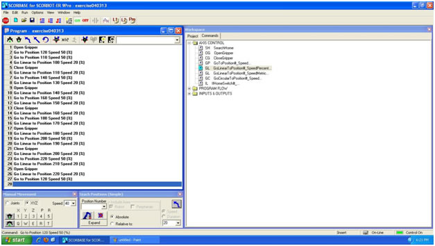
On the right side is the command screen (as shown in figure below) that shows the library of all the available robot commands in one place. Commands can be easily moved from the command library to the program window. All you have to do is to select a command from the right hand side and it will be automatically inserted into your program on the left. Write the Scorbase program using the recorded positions.
An illustrative example is given below on how to prepare a robot program using Scorbase.
Sample robot program
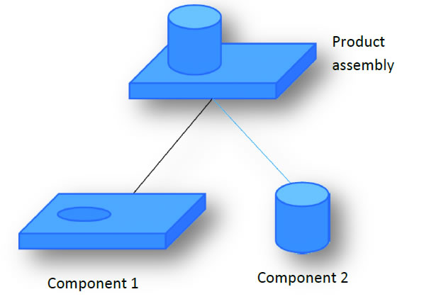
A sample program is given below for performing the assembly of the mechanical product assembly shown in Figure by using the Scorbase robot. The product assembly consists of two components:
component 1, which is a prismatic component with a hole and
component 2, which is a cylindrical component that is to be inserted into the hole.
Open Gripper
Go to Position 120 Speed 50 (%)
Go to Position 110 Speed 50 (%)
Go Linear to Position 100 Speed 20 (%)
Close Gripper
Go Linear to Position 110 Speed 20 (%)
Go to Position 140 Speed 50 (%)
Go Linear to Position 130 Speed 20 (%)
Open Gripper
Go Linear to Position 140 Speed 20 (%)
Go to Position 160 Speed 50 (%)
Go Linear to Position 150 Speed 20 (%)
Close Gripper
Go Linear to Position 160 Speed 20 (%)
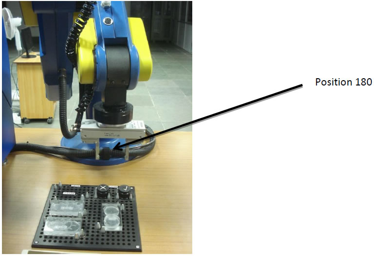
Go to Position 180 Speed 50 (%)
Go Linear to Position 170 Speed 20 (%)
Open Gripper
Go Linear to Position 180 Speed 20 (%)
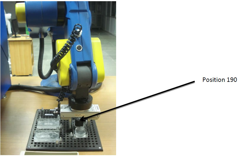
Go to Position 200 Speed 50 (%)
Go Linear to Position 190 Speed 20 (%)
Close Gripper
Go Linear to Position 200 Speed 20 (%)
Go to Position 220 Speed 50 (%)
Go Linear to Position 210 Speed 20 (%)
Open Gripper
Go Linear to Position 220 Speed 20 (%)
Go to Position 120 Speed 50 (%)
Consider the command line “Open Gripper”.
It indicates the command for opening the fingers of the gripper.
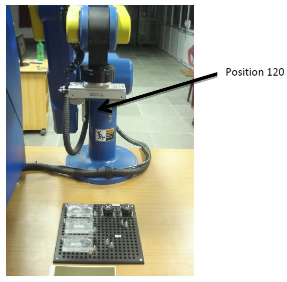
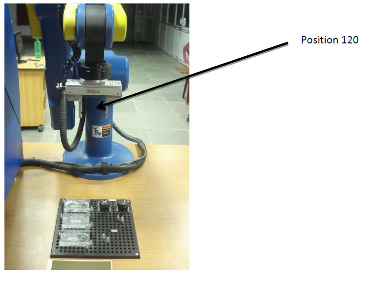
Consider the command line “Go to Position 120 Speed 50 (%)”.
It indicates the command for moving the robot gripper from its previous point (Home Position) to the end point P120 as shown in figure below at 50% of the maximum speed.
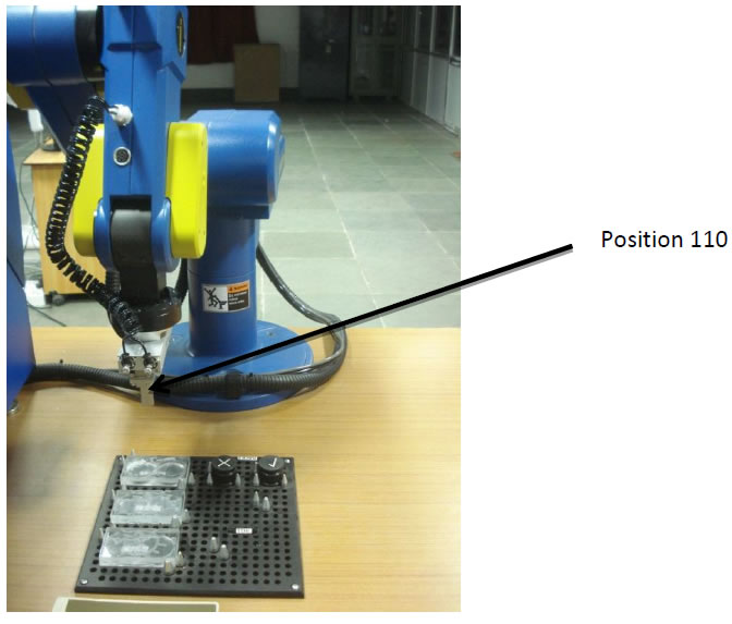
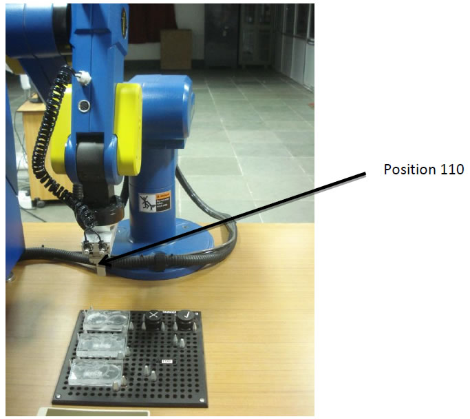
Consider the command line “Go to Position 110 Speed 50 (%)”.
It indicates the command for moving the robot gripper from its previous point (P120) to the new point (P110) as shown in figure below at 50% of the maximum speed.
Position 120
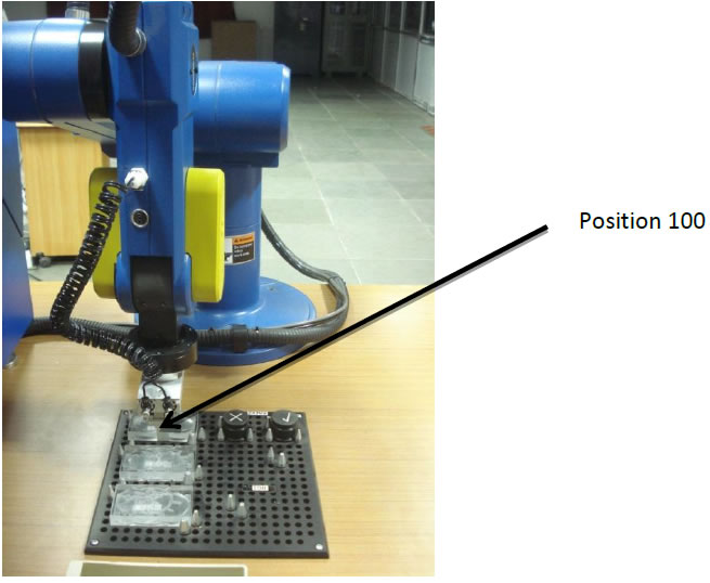
Consider the command line “Go Linear to Position 100 Speed 20 (%)”.
It indicates the command for moving the robot gripper in a linear path from its previous point (P110) to the new point (P100) as shown in figure below at 20% of the maximum speed.
Note: The gripper speed is reduced as it positions itself over the part for the purpose of gripping it.
Consider the command line “Close Gripper”.
It indicates the command for closing the fingers of the gripper.
Consider the command line “Go Linear to Position 110 Speed 20 (%)”.
It indicates the command for moving the robot gripper in a linear path from its previous point (P100) to the end point (P110) as shown in figure below at 20% of the maximum speed.
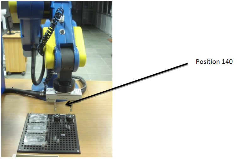
Consider the command line “Go to Position 140 Speed 50 (%)”.
It indicates the command for moving the robot gripper from its previous point (P110) to the end point (P140) as shown in figure below at 50% of the maximum speed.
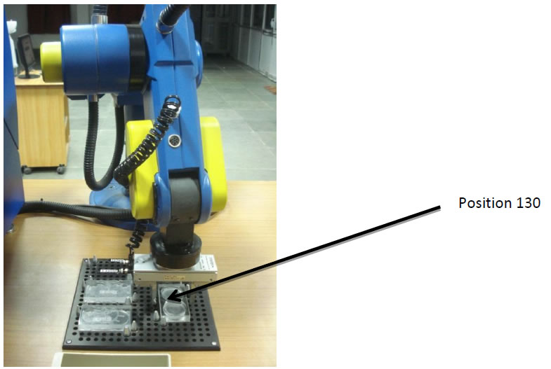
Consider the command line “Go Linear to Position 130 Speed 20 (%)”.
It indicates the command for moving the robot gripper in a linear path from its previous point (P140) to the end point (P130) as shown in figure below at 20% of the maximum speed.
Consider the command line “Open Gripper”.
It indicates the command for opening the fingers of the gripper.
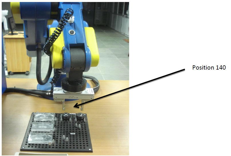
Consider the command line “Go Linear to Position 140 Speed 20 (%)”.
It indicates the command for moving the robot gripper in a linear path from its previous point (P130) to the end point (P140) as shown in figure below at 20% of the maximum speed.
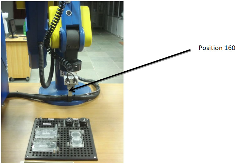
Consider the command line “Go to Position 160 Speed 50 (%)”.
It indicates the command for moving the robot gripper from its previous point (P140) to the end point (P160) as shown in figure below at 50% of the maximum speed.
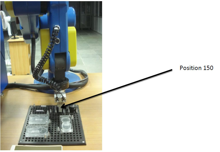
Consider the command line “Go Linear to Position 150 Speed 20 (%)”.
It indicates the command for moving the robot gripper in a linear path from its previous point (P160) to the end point (P150) as shown in figure below at 20% of the maximum speed.
Consider the command line “Close Gripper”.
It indicates the command for closing the fingers of the gripper.
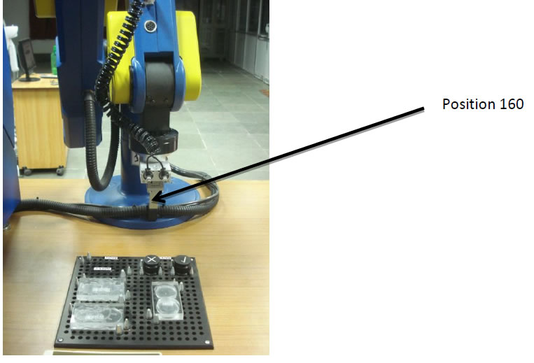
Consider the command line “Go Linear to Position 160 Speed 20 (%)”.
It indicates the command for moving the robot gripper in a linear path from its previous point (P150) to the end point (P160) as shown in figure below at 20% of the maximum speed.
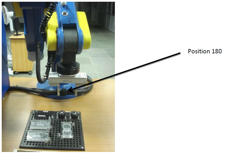
Consider the command line “Go to Position 180 Speed 50 (%)”.
It indicates the command for moving the robot gripper from its previous point (P160) to the end point (P180) as shown in figure below at 50% of the maximum speed.
Consider the command line “Go Linear to Position 170 Speed 20 (%)”.
It indicates the command for moving the robot gripper in a linear path from its previous point (P180) to the end point (P170) at 20% of the maximum speed.
Consider the command line “Open Gripper”.
It indicates the command for opening the fingers of the gripper.
Consider the command line “Go Linear to Position 180 Speed 20 (%)”.
It indicates the command for moving the robot gripper in a linear path from its previous point (P170) to the end point (P180) as shown in figure below at 20% of the maximum speed.
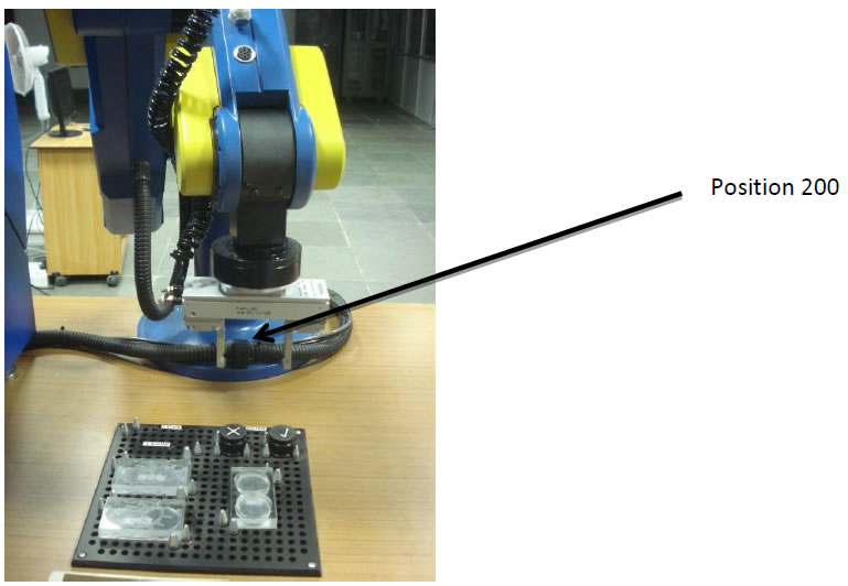
Consider the command line “Go to Position 200 Speed 50 (%)”.
It indicates the command for moving the robot gripper from its previous point (P180) to the end point (P200) as shown in figure below at 50% of the maximum speed.

Consider the command line “Go Linear to Position 190 Speed 20 (%)”.
It indicates the command for moving the robot gripper in a linear path from its previous point (P200) to the end point (P190) as shown in figure below at 20% of the maximum speed.
Consider the command line “Close Gripper”.
It indicates the command for closing the fingers of the gripper.
Consider the command line “Go Linear to Position 200 Speed 20 (%)”.
It indicates the command for moving the robot gripper in a linear path from its previous point (P190) to the end point (P200) as shown in figure below at 20% of the maximum speed.
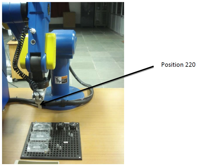
Consider the command line “Go to Position 220 Speed 50 (%)”.
It indicates the command for moving the robot gripper from its previous point (P200) to the end point (P220) as shown in figure below at 50% of the maximum speed.
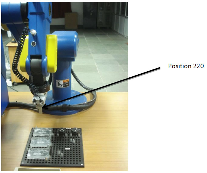
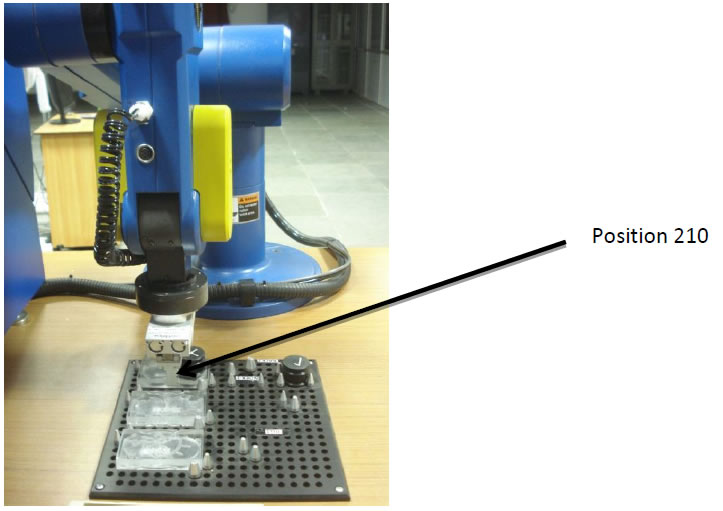
Consider the command line “Go Linear to Position 210 Speed 20 (%)”.
It indicates the command for moving the robot gripper in a linear path from its previous point (P220) to the end point (P210) as shown in figure below at 20% of the maximum speed.
Consider the command line “Open Gripper”.
It indicates the command for opening the fingers of the gripper.
Consider the command line “Go Linear to Position 220 Speed 20 (%)”.
It indicates the command for moving the robot gripper in a linear path from its previous point (P210) to the end point (P220) as shown in figure below at 20% of the maximum speed.
Consider the command line “Go to Position 120 Speed 50 (%)”.
It indicates the command for moving the robot gripper from its previous point (P220) to the end point (P120) as shown in figure below at 50% of the maximum speed.
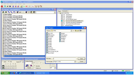
19. After entering the Scorbase program,save the project.
20.To execute a program select->file->open project and select the project file.
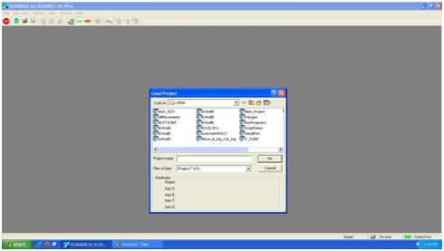
21. Befor running the program, make sure that you have click on the 1st line of the program . Next, select the mode of running the program by clicking on the appropriate Run icon in the toolbar as shown in figure below.
Steps for system shutdown
22. Make sure that all the produced parts are removed from the rack and new supplied parts are placed back in the rack.
23. Make sure that there is no part in the robot gripper.
24. Make sure that robot is in a safe place to Home.
25. Click on the Home icon.
26. Close the gripper.
27. Exit from the Scorbase software. Do not save.
28. Shut down the PC.
29. Turn off the robot controller.
30. Turn off the robot controller UPS.
31. Turn off the workstation 2 UPS.
32. Turn off the power supply.
33. Close the valve for compressed air supply.
34. Turn off the remote control switch for compressor.
For remote experimentation, please book a slot in advance.
Click here to view the available slots.
Click here for live video streaming of the experiment