 |
 |
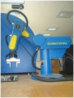
The robot has a manipulator arm having five revolute joints.
The five joints of the arm are the base, shoulder, elbow, pitch
and roll. The following figure shows the videos of movements of the five joints.
The robot is used in the CIM system for loading and unloading the CNC milling machine as well as the Quality Control station,for storing and retrieving the parts to/from storage racks, and for assembly.
The following are detailed specifications of the robot.
| Maximum Payload | 2kg |
| Number of Axes | 5 rotational axes and gripper |
| Axis 1 (Base rotation) | 276° |
| Axis 2(Shoulder rotation) | 153° |
| Axis 3(Elbow rotation) | 214° |
| Axis 4(Wrist pitch) | 202° |
| Axis 5(Wrist roll) | 737° |
| Type of control | PID |
| Path control | Joint; Linear; Circular |
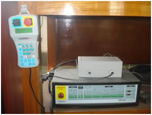
| Actuators | 24VDC servo motor on each axis |
| Position Feedback | Incremental optical encoders with index pulse on each axis |
| Transmission | Harmonic drives and timingbelts |
| Inputs | 16 digital inputs: 24V max., high/low configurable;4 analog inputs: input voltage 0-10V |
| Speed | 1.9 m/sec (74.8"/sec) |
| Repeatability | ± 0.05 mm (0.002") |
| Gripper | Pneumatic: Max. opening: 64 mm (2.5") |
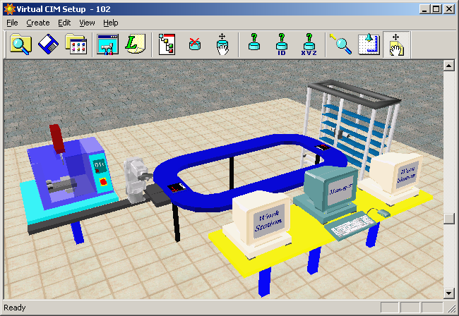
The CIM cell that has been designed for the simulation experiment consists of
• a CNC Milling machine,
• a pneumatic vise for building the assembly,
• a quality control station with camera and image processing system for automated inspection,
• a five axis robot with a linear sliding base for performing assembly as well as material handling tasks such as loading/unloading the CNC machine, the quality control station and the storage racks, and
•storage racks for storing the raw materials, work-in-process inventory as well as finished products.
To run a remote simulation experiment, perform the following steps:
1. First install the Web Viewer client by clicking
here to download the executable file and Select run in order to run this program from its current location.
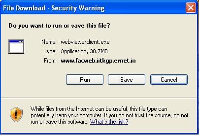
The Web Viewer Client Setup window will be displayed. When the installation is complete, click Finish
2.Select Save in order to save this program to a specified directory for future installations.
3.Open the Internet Explorer (version 6.0 and higher), and enter the following IP address in the address field:
http://www.cimlab.iitkgp.ernet.in/intellitek/start.asp
(Note: The Web Viewer application enables you to remotely access a specific CIM cell and track the production cycle from the various view tabs.)
A webpage will be displayed as follows.
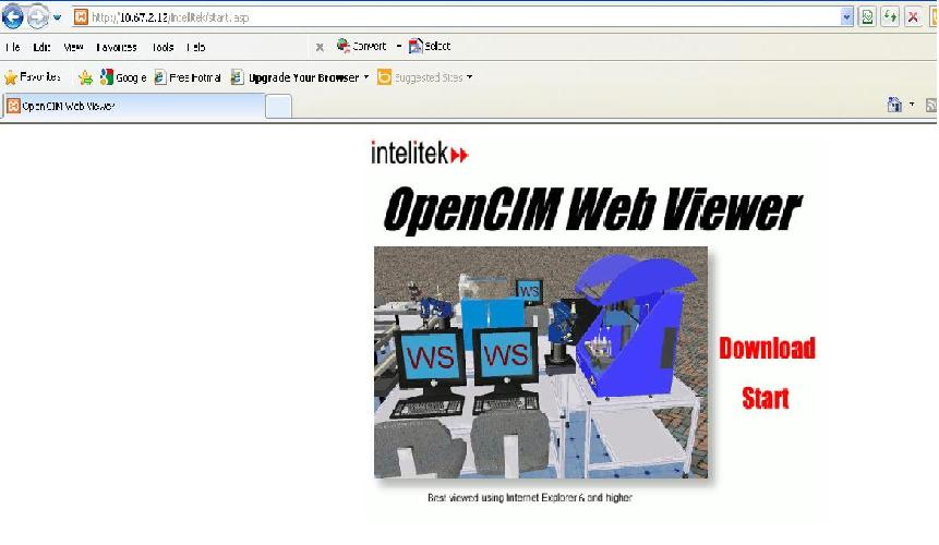
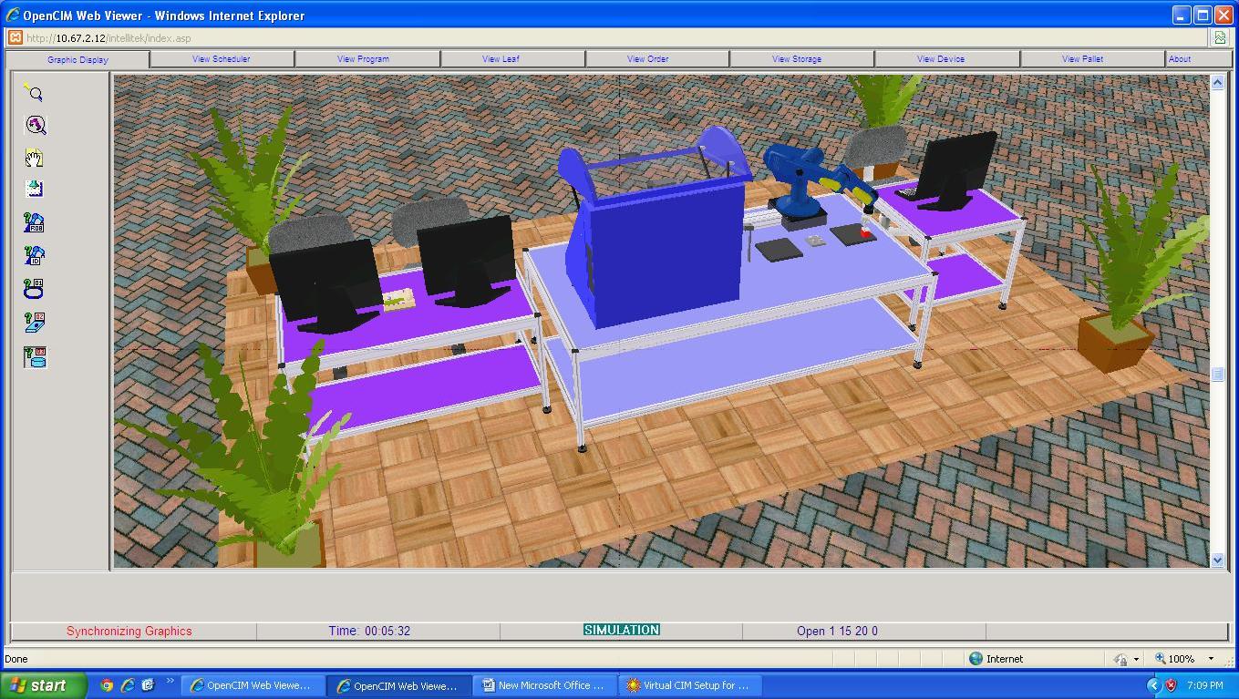
4. Click Start. The Open CIM Web Viewer appears displaying the Graphic Display Window as shown below with the following tabs to help in tracking the CIM production cycle.
• Graphic Display Tab to show a 3D display of the operations being performed in the CIM cell.
• View Scheduler Tab to display the scheduler information of the CIM cell.
• View Program Tab to display the A-Plan (meaning, the production work order) of the CIM cell.
• View Leaf Tab to display the production activities in the CIM cell.
• View Order Tab to display the current manufacturing order.
• View Storage Tab to display the current location of parts in the CIM cell.
• View Device Tab to display the actions performed by system devices.
• View Pallet Tab to display the pallets in the CIM cell and the current status of each pallet.
• Web Viewer Status Bar to display CIM cell information, such as current status, elapsed time, etc.
• View About Tab to display dialog with information about Web CIM Viewer software and CIM software of the Cell that is currently in view.
For details on how to use the above tabs for tracking the CIM production cycle, please refer to the video tutorials given in the User Guide page.
1.What are the material handling tasks necessary to perform in a typical CIM cell?
2.How can you automate loading and unloading of a CNC machine tool?
3.How can you automate the part handling at the quality control station?
4.Determine which of the following items need to be stored in a storage device?
5.Which of the following viewing options redefines the center of the graphic viewing image?
6.Which one of the following viewing options enables you to focus on the location of specific part during production cycle?
7.Which one of the following viewing options places camera in the center of the cell ceiling facing downwards?
8.Does the production data that is displayed in the device view enable you to identify the action performed in the cell as they occur in the production cycle?
9.Does the storage view enable you to see the exact location of a part at any time during the production cycle?