•To demonstrate automatic generation of CNC part program from a CAD model and verification of the tool path by simulation.
• To demonstrate the machining operation on a 3 axis CNC Milling machine by downloading the Part program generated above to the CNC machine for execution
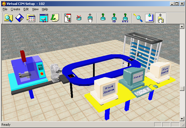
SpectraCAD Engraver
Avaliable soon
The set-up consists of the following:
• CAD/CAM software for automatic generation of CNC part program from CAD model
• 3-axis vertical CNC Milling machine,
with aual axis pneumatic vise for work holding,
and 4 station automatic tool changer (For details, visit the Lab Facilities page by clicking here)
• Software for simulation of tool path (For details,visit the Lab Facilities page by clicking here)
Preparation of Part Program:
1. Start spectraCAD by double clicking spectraCAD icon or by selecting spectraCAD from the Program list under Start menu.
2. Select the Units command under the Engraving menu and choose Milimeters
3. Select Engraving Set up from Engraving Menu. The Engraving Setup panels appear,this six panels allow you to create or edit settings for materials, tools, and files that are used by the program when an engraving NC file is generated.
4. Select Material type from the Edit Material tab.
Go to Tool Library tab and select a tool number from the tool library list.
Select a tool type, such as End Mill from the Tool Type drop-down menu.
Selet Station number from the drop-down menu.
Enter a name in the description field.
Enter the number of teeth (Num Teeth) the tool should have.
Enter the Material Type from which the tool is made
Enter a tool Diameter.
Enter a tool Height/Offset value.
Enter a Diameter Offset.
Apply the new parameters to the selected tool number by clicking the Apply button
4.Go to Post Processor tab and select the post processor file as SpectraM.pst from the Posts list to generate CNC code for the milling machine. Click on OK.
5. Go to Stock Size tab and change the Stock size and the origin of the workpiece by using the Stock Size dialog box. In the present case, change the dimension to X Dim 90, Y Dim 50, Z Dim 15 and change the origin to X 0, Y 0, Z 0. Click on OK to accept the new Stock Dimension.
5. Go to View->Show->Untick Grid
6. Go to View->Zoom all
7. View->Toolbars->Show Draw|Snap|Engrave
8. Draw using Draw Tool bar
9. Click on ![]() icon or select Engrave command from the engraving menu to dispaly a series of dialog boxes that guide you through the process of generating an NC part program for engraving.
icon or select Engrave command from the engraving menu to dispaly a series of dialog boxes that guide you through the process of generating an NC part program for engraving.
The dialog boxes appear in the following order:
Select Geometry
Seelect Cutting Parameters
Engraving Job Summary
Generate NC file.
The Select Geometry dialog box as shown in figure (insert snapshot of engraving window)allows you to select and name any or all of the entities in the current drawing for engraving. Choose the option, Select All Geometry and Text to select every entity in the drawing, and click on the Do Selection button.The number of entities selected will be shown.
10. Click the Next button to open Select Cutting Parameters dialog box as shown in figure(insert scrrenshot).This dialog box allows you to enter parameters for the cutting method,the feed rate and the spindle speed.
Enter the Final Depth (finished depth of engraving) as 2
Enter the Depth Increment (depth of each step required to reach the final depth) as 2.
Enter the Rapid Height (the height to which the cutting tool moves just prior to the rapid traverse motion) as 2
Enter Top of Stock Z(location of the stock surface on the Z axis) as 0.
Uncheck the optionFinsh Pass. Uncheck the option Automatic and enter Feed Rate as 100, Spindle Speed as 2000, and Plunge Rate as 50
Click the Next button to load Engraving Job Summary dialog box as shown in figure(insert screenshot).
Click Next button to open the dialog box, Genrate NC File as shown in figure(insert screenshot).
11. Click on the Finish button to genrate the NC file and exit the dialog box.
12. Save the NC file.
Running the CNC part program
1. Open CNCBase Software.
2. Select File>Open to open the NC file genrated by spectraCAD.
3. To check for programming errors before running a part program select verify program
4. Watch the Verify window for simulation of the tool path.
5.When the verification is completed,the normal program stop dialog box appears.
6. Before you perform machining you must establish a point of origin at the ends of travel of the machine. The machine uses the point called machine home as a reference for all machine co-ordinate movement and work co-ordinate settings.
To set machine home:
Select setup > Set/check home,the Machine home/reference dialogue box will appear
7. Click Set home.The machine will move the axes to the positive end of travel(home position)
8. Set the point of origin.
9. Using tool path verification,you can check for programming errors before running a part program. select Program > verify.The verify program dialogue box appears.
10. Check verify program then watch the verify window.
11. When the verification is completed,the normal program stop dialogue box appears.Click OK.
12. Before executing the program, make sure all safety procedure have been taken.
13. Select run/continue command from the program menu,The run program dialogue box appears.
14. Make sure that the Start Line box is set to line 1of the program.
15. Click the run settings buttons.The Run setting dialogue box appears.
16. Make desired changes in the Run setting dialog box, and select OK.
17. Check run button to begin run your program.
18. After the part is completed ,wait until all operation have stopped before opening the safety shield and removing the completed part.
For remote experimentation, please book a slot in advance.
Click here to view the available slots.
Click here for live video streaming of the experiment