-
Objectives
- •To demonstrate tool path planning for machining, generation of CNC part program containing G codes and M codes by manual part programming, and verification of the tool path by simulation.
- • To demonstrate the machining operation on a 3 axis CNC Milling machine through 3-D graphical animated simulation.
CNC
Computer Numerical Control (CNC) is a form of programmable automation, in which the mechanical actions of a machine tool are controlled by a program containing coded alphanumeric data the alphanumeric data represent the relative positions between the cutting tool and the workpart as well as other instructions needed to operate the machine.
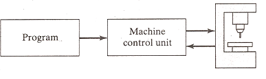
A CNC system consists of three basic components:
• the program of instructions or part program,
• the machine control unit (MCU), and
• the CNC machine tool .
Part program
The program of instructions, also called a part program, is the detailed step by step commands that direct the actions of the machine tool. The individual commands refer to positions of a cutting tool relative to the worktable on which the workpart is fixtured. Additional instructions include spindle speed, feedrate, cutting tool selection, and other functions.
The programmer prepares the NC code in low level machine language. The CNC code consists of blocks (also called lines), each of which contains an individual command for a movement or specific action. Each block is numbered. There are two major types of CNC codes in any program.
G codes and M codes
G-codes: They are preparatory functions, which involve actual tool moves (e.g. control of the machine tool). These include rapid moves, feed moves, dwells, roughing and profiling cycles
M-codes: They are miscellaneous functions, which include actions necessary for machining, but not those that are an actual tool movement (e.g. auxiliary functions). They include spindle on and off, program stops, and other similar related functions.
Machine Control Unit : The Machine Control Unit (MCU) consists of a microcomputer and related control hardware that stores the program of instructions and executes it by converting each command into mechanical actions of the machine tool. The related hardware of MCU includes components to interface with the machine tool and feedback control unit. The MCU also includes control system software, calculation algorithms, and translation software to convert the NC part program into a usable format for the MCU.
CNC Machine Tool
The third basic component of the CNC system is the machine tool. It performs the processing steps to transform the starting work material into a completed part. Its operation is directed by the MCU, which in turn is driven by instructions contained in the part program. It consists of worktable, spindle as well as the motors and control to drive them.
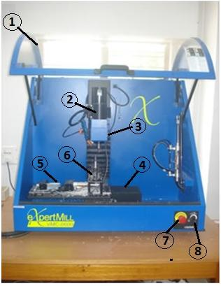
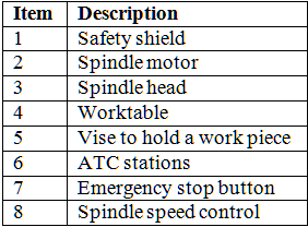
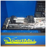
A Vertical Machining Centre |
|
The figure above shows a three axis Vertical Machining Centre. It is the most common type of machining centre used and will be the type seen in this training program. It is called a Vertical Machining Centre because the orientation of the machine tool spindle is vertical. It is primarily employed for performing milling operation using rotating tools but it is often also capable of various other operations like drilling, boring, tapping. Plane and sculptured (3 –D) surfaces can be machined. The material to be machined is usually clamped to a table called the worktable.The table moves in the XY plane. As the operator faces the machine the X-axis movement moves the table left-right.Fig. shows a video of X axis movemenet.
The video shows the action of opening and closing of the jaws of the vise.
Many different types of tools are generally needed to create the various features of a workpiece. In a machining centre, these tools are commonly held in a tool storage device. The device which is used to automatically remove a tool from the spindle and load a new tool from the tool storage device is called an Automatic Tool Changer (ATC). Figure shows an ATC used on a Vertical Machining Centre.
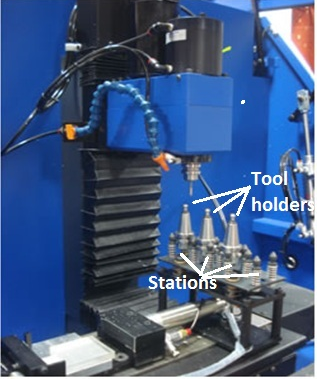
A 4 station ATC
The machine has a pneumatically actuated safety shield which can be opened and closed. A video of the opening and closing action of the safety shield is shown in the following figure.
Using the information contained in the part program, the CNC Machining Centre controls the various axis movements,opens and closes the shield, starts and stops the spindle, sets the spindle speeds, sets the rate at which the tool feeds into the workpiece, and even changes the tools. All of the operations and functions of the machine tool are performed by motors. The motors are controlled by the Machine Control Unit as it runs the part program.
Experimental Set-up
The set-up consists of the following
•3-axis vertical CNC Milling machine, with dual axis pneumatic vise for work holding, and 4 station automatic tool changer (For details, visit the Lab Facilities page by clicking here
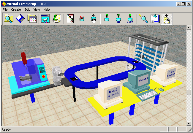
• Software for simulation of tool path (For details, visit the Lab Facilities page by clicking here
1.For accessing this page, you need to log on to the course website http://www.learnmate.iitkgp.ernet.in/login/index.php
Provide username and password to log in to the system.
2. Alternatively, create a new username and password by self enrolling to the system using an enrollment key for this experiment.
3. If you have not received enrollment key for this experiement then send us an e-mail at cimlab.iitkgp@gmail.com for obtaining an enrollment key .