Experimental study
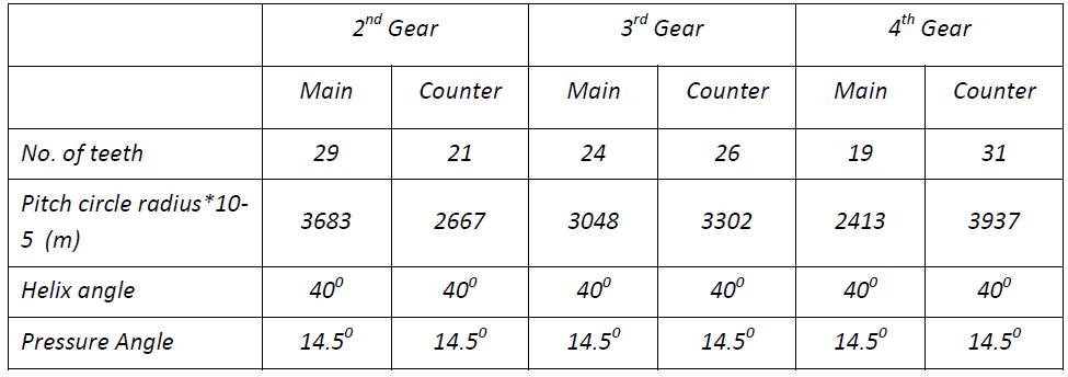
The experimental set up (shown in Fig. 1) consists of a 7.5kW, two-pole, and three-phase induction motor coupled to a 4-speed automobile gearbox. Speed of the induction motor is controlled by a Variable-Voltage-Variable-Frequency Drive (VVVFD). The output shaft of the gearbox is connected to a separately excited D.C. motor by a constant-velocity joint. The DC motor acts as a generator. A 5.625kW variable resistor load bank is connected with this DC motor. With this load bank 15 different kinds of loads can be applied ranging from 0 to 5.625kW in the interval of 0.375kW. The load on the gearbox can be changed by varying the resistance load with the help of electrical switches. The four-speed transmission gearbox (shown in Fig. 2) has 2nd, 3rd and 4th gears as synchro meshed gears. The detailed specification of the transmission gearbox is shown in Table 1 .
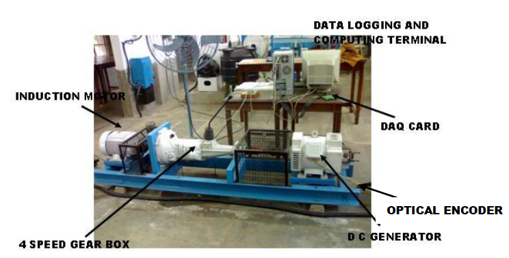
Fig 1: Experimental setup
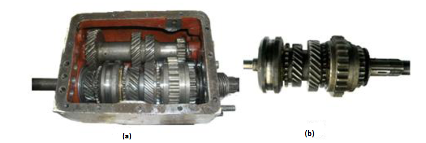
Fig 2: a) 2-stage Synchromesh gearbox b) Output gear shaft with 2nd gear (healthy)
Table 1: Specification of the gears
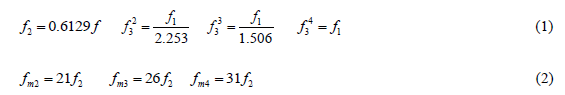
The input speed of gearbox is the mechanical speed of induction motor (f1).The lay shaft speed (f2), output shaft frequency (f3) and tooth meshing frequencies (fm2, fm3 and fm4) can be calculated by using equation 1 & 2.
The line diagram of the gear meshing is shown in Fig 3.
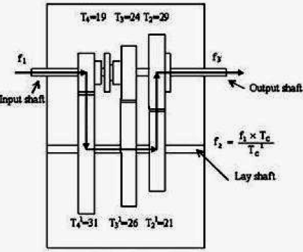
Fig 3: Line diagram of meshing during 2nd gear operation


.gif)