Objective
This experiment is used to determine the frequency response of a mechanical system. The mechanical system in this case could be three dimensional beam with various boundary conditions. The following can be understood from this experiment.
Frequency response of following three types of beams
1. Cantilever beam
2. Fixed beam
3. Simply supported beam
First five natural frequencies of in-plane modes of 3-D beam of 30 cm length.
Introduction
Modal analysis is the study of the dynamic responses of mechanical systems under vibrational excitation by an input force.
By modal analysis, the modal parameters such as resonant frequency, mode shapes and damping of a structure can be measured to construct a modal of the resonance. To study the dynamic response of the systems are composed of transducers (typically accelerometers and load cells), an analog to digital converter (to digitize analog instrumentation signals) and an output device i.e., host PC to view the data and analyse it.
To explain this in a simple manner, we'll take a plate as an example. We'll apply a force that varies in a sinusoidal fashion on one corner. Then we'll change the rate of oscillation (frequency rate) of the sinusoidal force, but the peak force stays the same and then, we'll simultaneously measure the response of the excitation with an accelerometer attached to the other cornet of the plate.

The measured amplitude can vary depending on the frequency rate of the input force. The response amplifies as we apply a force with a frequency rate that gets closer and closer to the system's resonant or natural frequencies.
The resonant frequency is the frequency at which any excitation produces an exaggerated response. This is important to know since excitation close to a structure's resonant frequency will often produce adverse effects. These generally involve excessive vibration leading to potential fatigue failures, damage to the more delicate parts of the structure or, in extreme cases, complete structural failures.
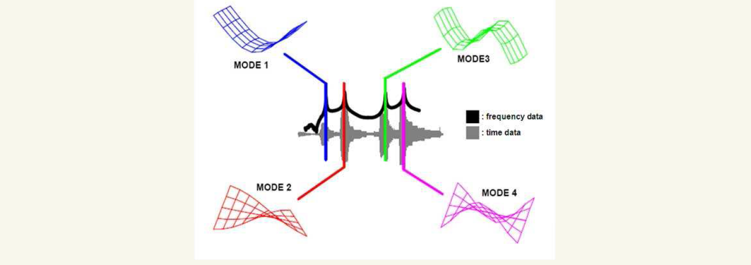
If we take the time data and transform it to the frequency domain using a Fast Fourier transform algorithm to compute something called the "frequency response function", we see the functional peaks that occur at the resonant frequencies of the system.

Deformation patterns (bending, twisting etc.) at these resonant frequencies take on a variety of different shapes depending on the excitation force frequency. These deformation patterns are referred to as the structure's mode shape.
The Tacoma Bridge was collapsed due to the resonant vibration of the torsional mode as shown in fif. By providing the structural damping we can eliminate like these catastrophes to dissipate the vibration energy of the structure and return ti rest quickly after the load removal.
How can we do modal analysis?
Modal analysis refers to a complete process including both an acquisition phase and an analysis phase. The structure is excited by external forces such as an impact hammer or shaker. In this case, we talk about experimental modal analysis.
Modal testing systems consist of transducers (typically accelerometers and force cells), an analog to digital converter or frond end to digitize the analog instrumentation signals and a host PC to review and analyse the data.
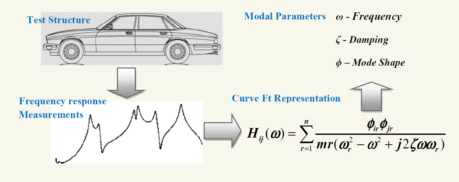
Above figure shows that how the modal analysis is carried out for a car when electronic shaker is provided to provide vibrational excitation. Frequency response can be obtained by host PC or oscilloscope by digitizing the amplitude signals which are measured through transducers. Finally modal parameters are obtained by the curve filling of the frequency response.
Operational Modal Analysis complements traditional analysis methods. It only measures the resonse of test structures under actual operating conditions. It is used to test cars, airplanes, wind turbines and any other application s that are difficult or even impossible to excite by external force, owing to boundary conditions or sheer physical size. Modal testing results can also be used to correlate simulation analysis and create a 'real life' simulation model.
To guarantee realistic high fidelity simulations, it is essential that simulation models meet stringent accuracy standards. Ensuring reliable simulation results requires component, subsystem and full system models to be compared with experimental data, or alternatively validated models of similar structures. Building and validating system models from the bottom up is the only way to prevent accumulating of assumptions made regarding material properties, connections, joints and boundary conditions.
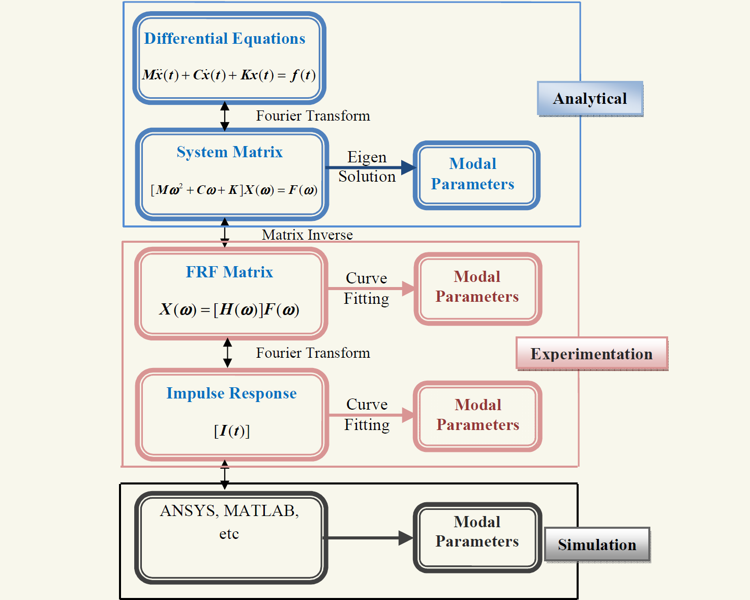
Methods of modal analysis can be divided into three types
Spatial model analysis - Analytical model
Response model - Experimentation
Modal model analysis - Simulations
The algorithm for above methods of modal analysis as shown in above fig.
Why should you use modal analysis?
Modal analysis helps to understand how a structure vibrates(frequency, damping and mode shapes).
Modal analysis can be used for:
1.Troubleshooting :
- Direct insight into the root cause of vibration problems.
2. Simulation and prediction :
- Find structural flexibility properties quickly
- Monitor incremental structural changes
3. Design Optimization :
- Design according to noise and vibration targets
- Enhance performance and reduce component and overall vibration
- Fast, test based evaluation of redesign for dynamics
4. Diagnostics and health monitoring :
- Confirm product quality from the production line and in the field.
,