Experimental study
Motor current signature using a machine fault simulator is shown in Fig 1 and Fig 2
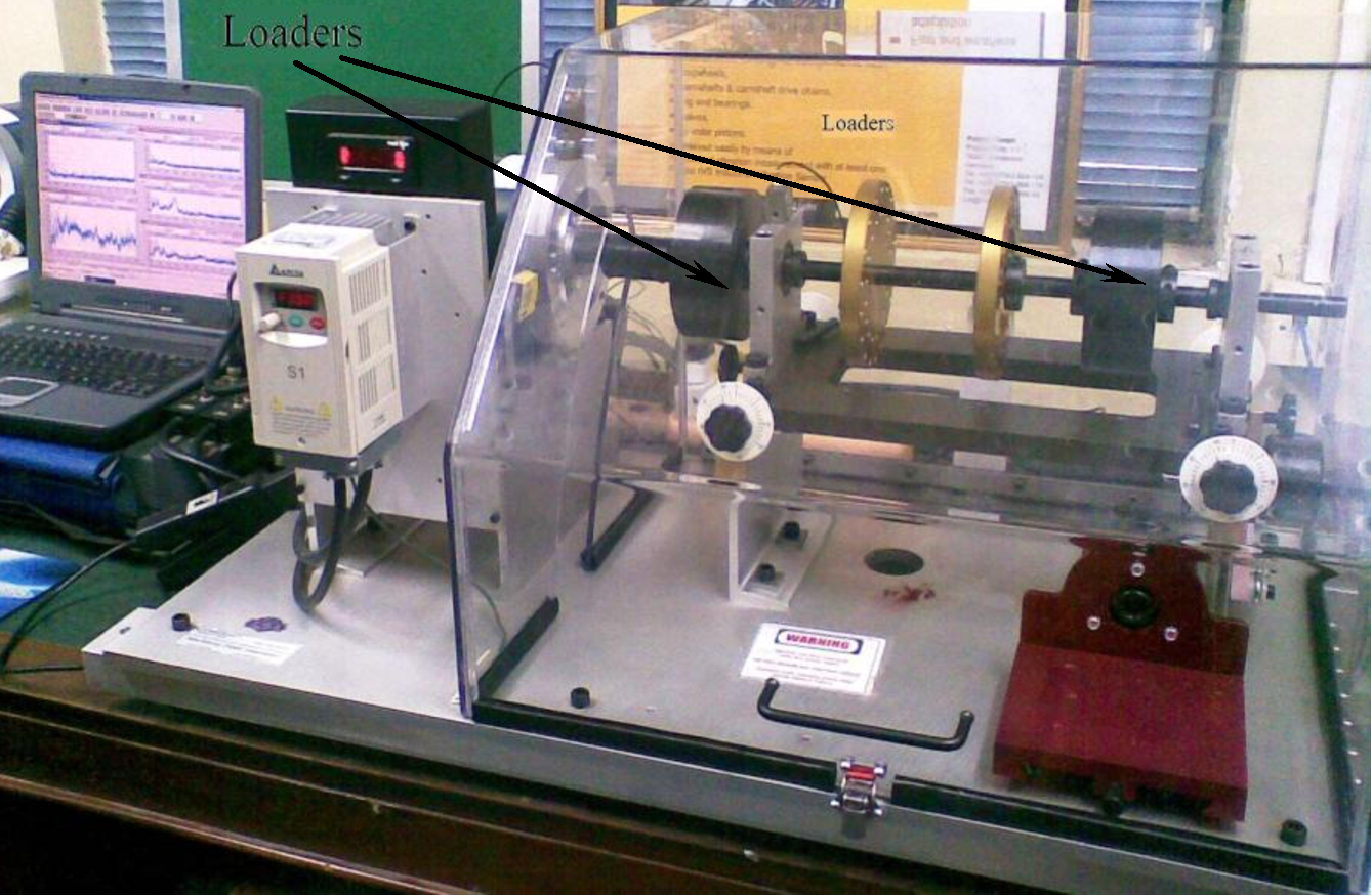
Fig 1: Front view of Machine fault simulator
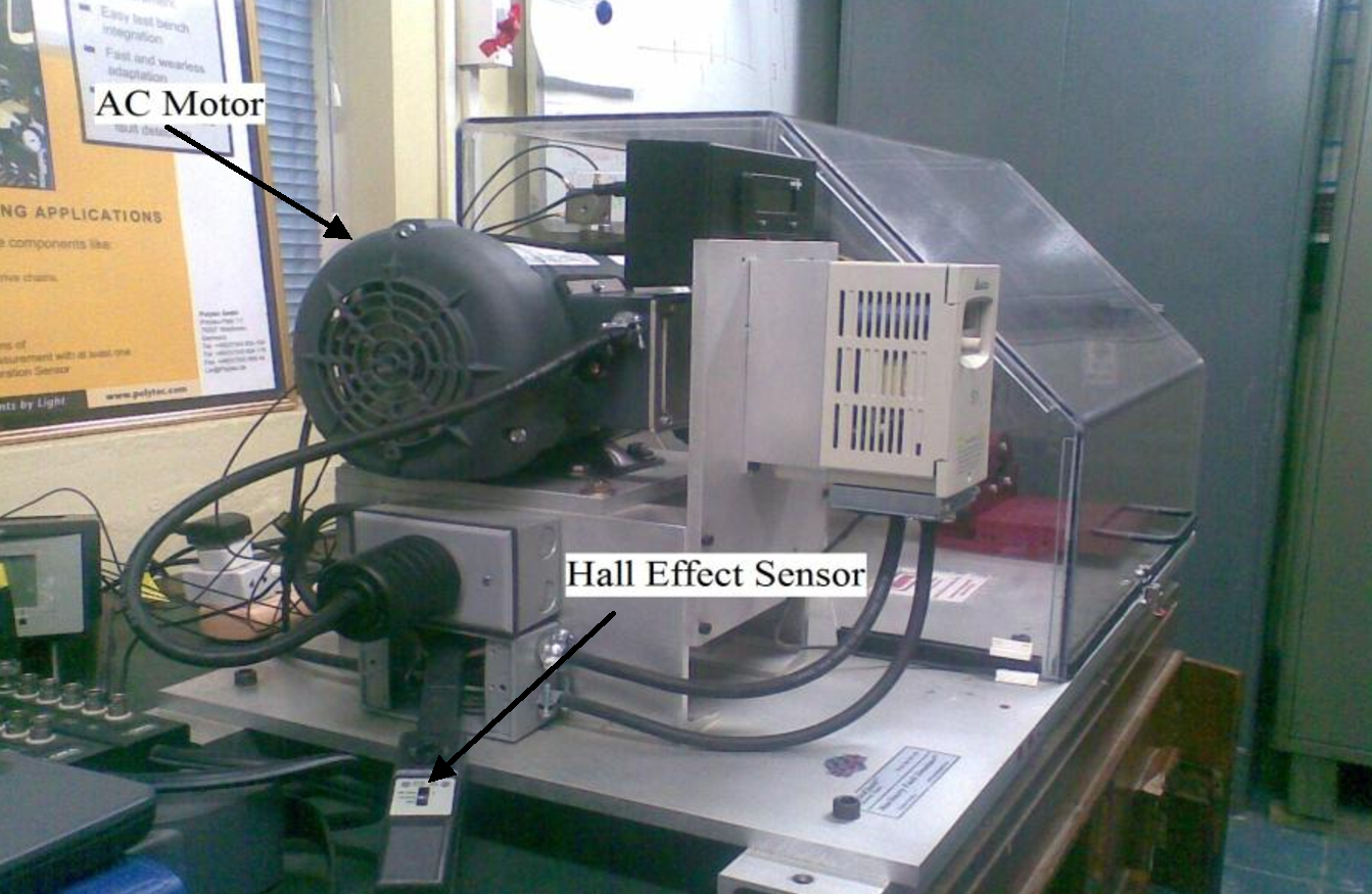
Fig 2: Side view of Machine fault simulator
In the machine fault simulator a 3 Phase, 1 H.P. AC motor is used. The machine fault simulator has 2 loaders each having 3/4 bore and weighting 11lb (5kg) are mounted on shaft to load the bearings. A Tektronix A622 Hall Effect sensor is used for measuring the induction motor current signals as shown in Fig 2.
The machine fault simulator has a digital display which provides the supply frequency to the induction motor, which happens to be the synchronous speed. There is also a optical probe to measure the actual motor mechanical speed. Thus by the motor slip can be calculated.
Observations were recorded when the motor was made to operate at three cases of synchronous speeds of 30, 38 and 47 Hz.
Specification
Table 1: Specifications of machine fault simulator
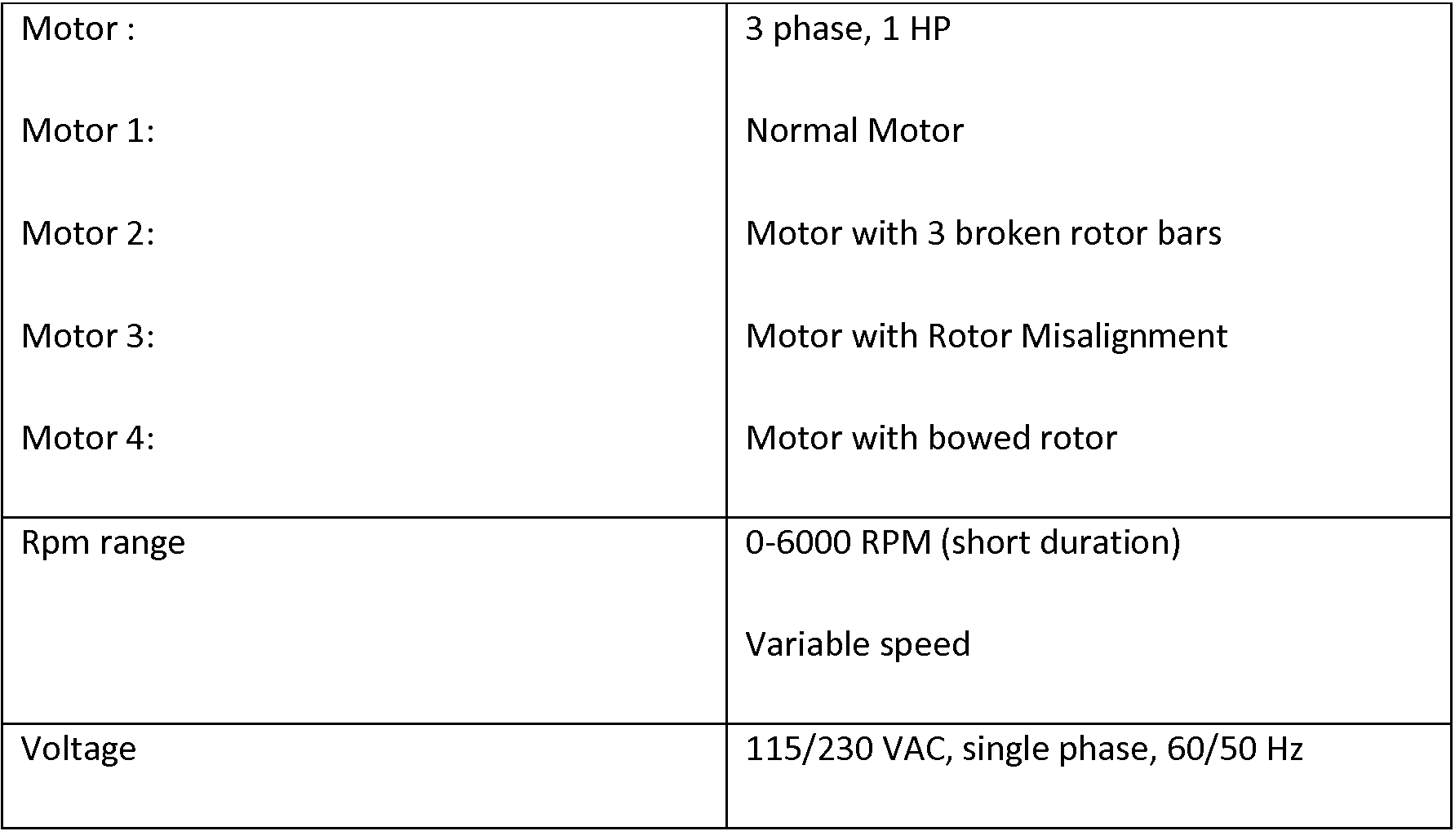
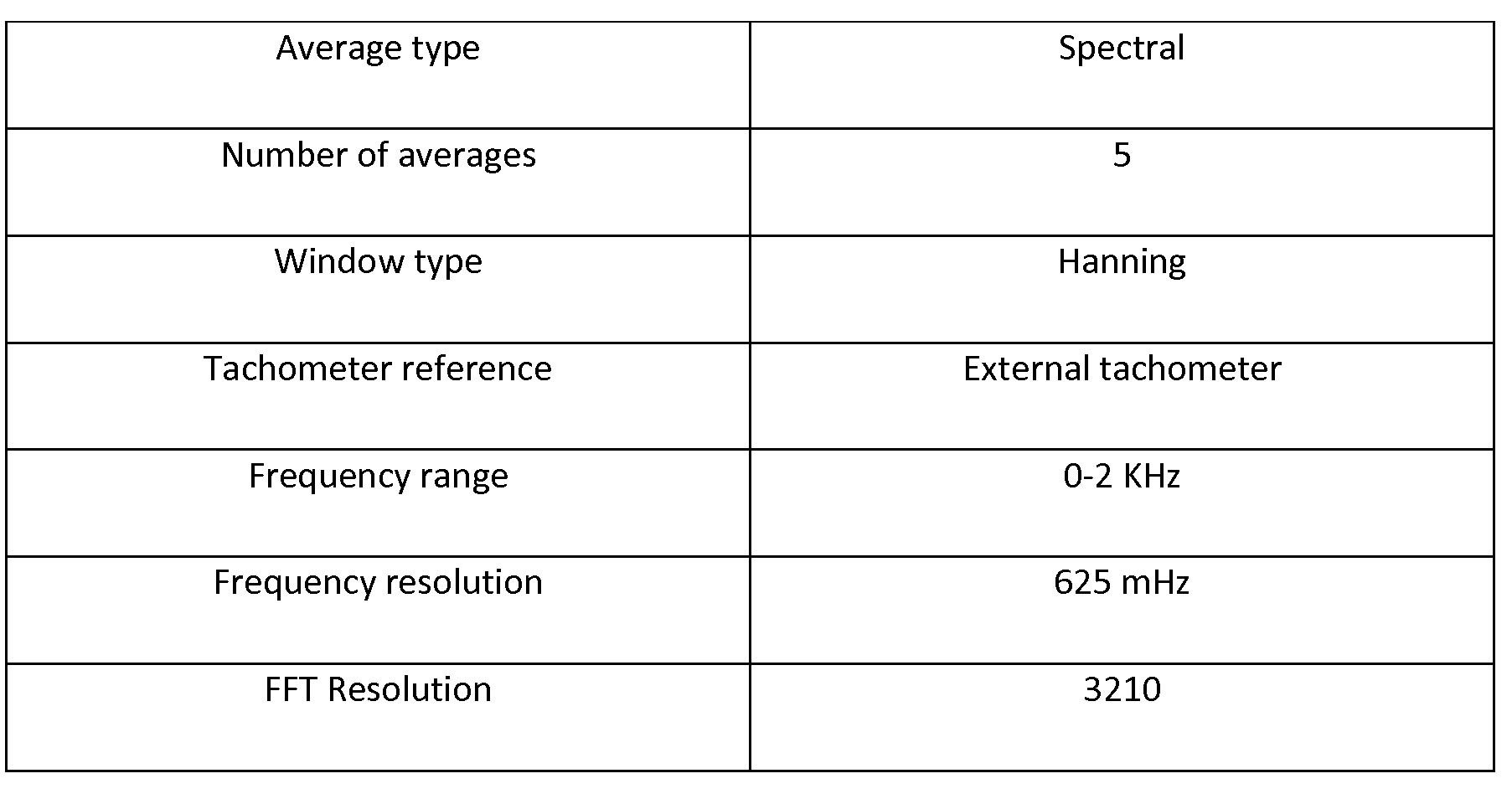
Table 2: Motor Current Signature Setup
(Application for OROS OR763)
 Test1:The first test with a Normal AC motor.
Test2:The second test with AC motor with built-in broken rotor.
Test3:The third test with AC motor with built-in bowed rotor
Test4:The fourth test with AC motor with rotor misalignment


.gif)